ENGINE
DISASSEMBLY
8. With
the
hoses disconnected,
remove
the
thermostat
housing
and
housing gasket, leaving the temperature
sender in place.
9. Remove
the
coolant circulating
pump.
Refer to
COOLANTPUMPASSEMBL~
10. Remove
the
air intake silencer
and
the
intake
manifold.
11.
Remove
the
oil filter
and
the
mounting
bracket
from
the
engine block.
12.
Unbolt
the
elbows
and
remove
the
exhaust
manifold
in
its entirety.
Remove the exhaust manifold/expansion
tank
in its
entirety. Disassemble separately,
clean
aU
surfaces, install
new gaskets when assembling. Use good quality gasket
cement.
NOTE:
Early
versions
were
an
assembly,
later versions
are
a
cast
unit.
(Cast units
are
only available
today).
14. Remove
the
engine
mounted
fuel filter with electric
fuel
lift
pump
and
related
lines.
NOTE:
The
positions
of
the
sealing washers that attach fuel lines
to
the
fuel
filter;
the
injection pump and the electric fuel
pump.
15. Remove
the
fuel injection
pump.
Disconnect the fuel injection pipes and fuel leak-off pipe
from the fuel injection pump and nozzles.
NOTE:
Put plugs or caps
on
the openings
of
the
injection pump
and
nozzle
connectors.
Golf tees work well
as
plugs.
16. Remove
the
fuel injection nozzles. Loosen the fuel
injection nozzles with a wrench. Remove the nozzles and
gaskets from the cylinder head.
·
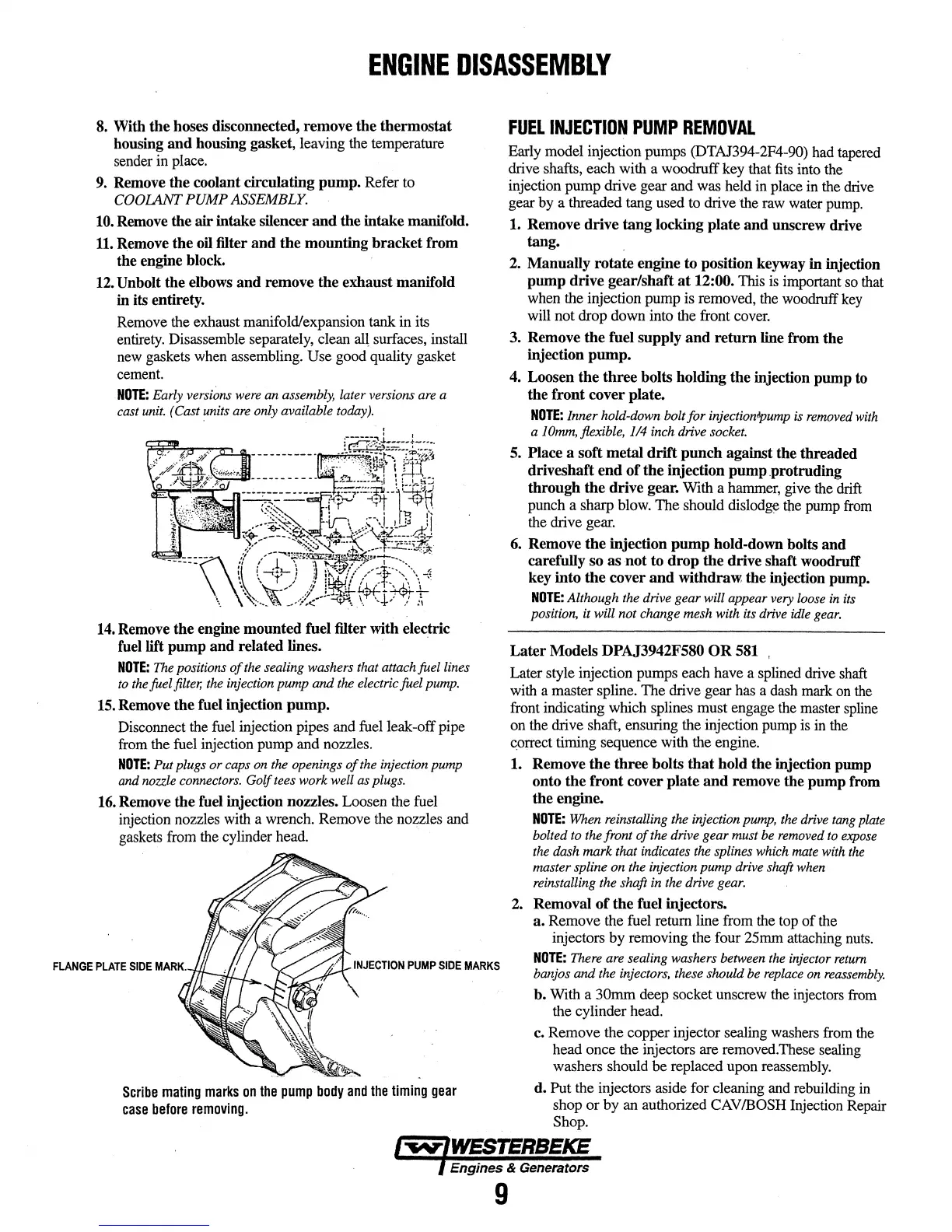
Scribe
mating
marks
on
the
pump
body
and
the
timing
gear
case
before
removing.
FUEL
INJECTION
PUMP
REMOVAL
Early model injection pumps (DTAJ394-2F4-90) had tapered
drive shafts, each with a woodruff key that
fits
into the
injection
pump
drive gear and was held in place in the drive
gear by a threaded tang used to drive the raw water pump.
1. Remove
drive
tang
locking
plate
and
unscrew drive
tang.
2.
Manually
rotate
engine to position keyway
in
injection
pump
drive
gear/shaft
at
12:00. This is important so that
when the injection pump is removed, the woodruff key
will not drop down into the front cover.
3. Remove
the
fuel supply
and
return line from
the
injection
pump.
4. Loosen
the
three
bolts holding
the
injection
pump
to
the
front
cover
plate.
NOTE:
Inner hold-down bolt for
injection~ump
is
removed
with
a
JOmm,
flexible,
114
inch drive
socket.
5. Place a
soft
metal
drift
punch
against
the
threaded
driveshaft
end
of
the
injection
pump
_protruding
through
the
drive
gear. With a hammer, give the drift
punch a sharp blow. The should
dislod~
tbe pump from
the drive gear.
6. Remove
the
injection
pump
hold-down bolts
and
carefully
so
as
not
to
drop
the
drive
shaft
woodruff
key
into
the
cover
and
withdraw.
the
injection pump.
NOTE:
Although
the
drive gear will appear
very
loose
in
its
position, it will not change mesh with
its
drive
idle
gear.
Later
Models DPAJ3942F580
OR
581 ,
Later style injection pumps each have a splined drive shaft
with a master spline. The drive gear has a dash mark on the
front indicating which splines must engage the master spline
on the drive shaft, ensuring the injection pump is in the
~orrect
timing sequence with the engine.
1. Remove
the
three
bolts
that
hold
the
injection
pump
onto
the
front
cover
plate
and
remove
the
pump
from
the
engine.
NOTE:
When
reinstalling the injection
pump,
the
drive
tang
plate
bolted
to
the
front
of
the drive gear must
be
removed
to
expose
the
dash mark that indicates
the
splines which
mate
with
the
master spline on the injection pump drive shaft
when
reinstalling the shaft
in
the drive
gear.
2. Removal
of
the
fuel injectors.
a.
Remove the fuel return line from the top
of
the
injectors
by
removing the four
2Smm
attaching nuts.
NOTE:
There
are
sealing washers between
the
injector
return
banjos and the injectors, these should
be
replace
on
reassembly.
b.
With a 30mm deep socket unscrew the injectors from
the cylinder head.
c.
Remove the copper injector sealing washers from the
head once the injectors are removed.These sealing
washers should be replaced upon reassembly.
d. Put the injectors aside for cleaning and rebuilding
in
shop
or
by an authorized
CAV
/BOSH Injection Repair
Shop.
~
WESTERBEKE
9
 Loading...

