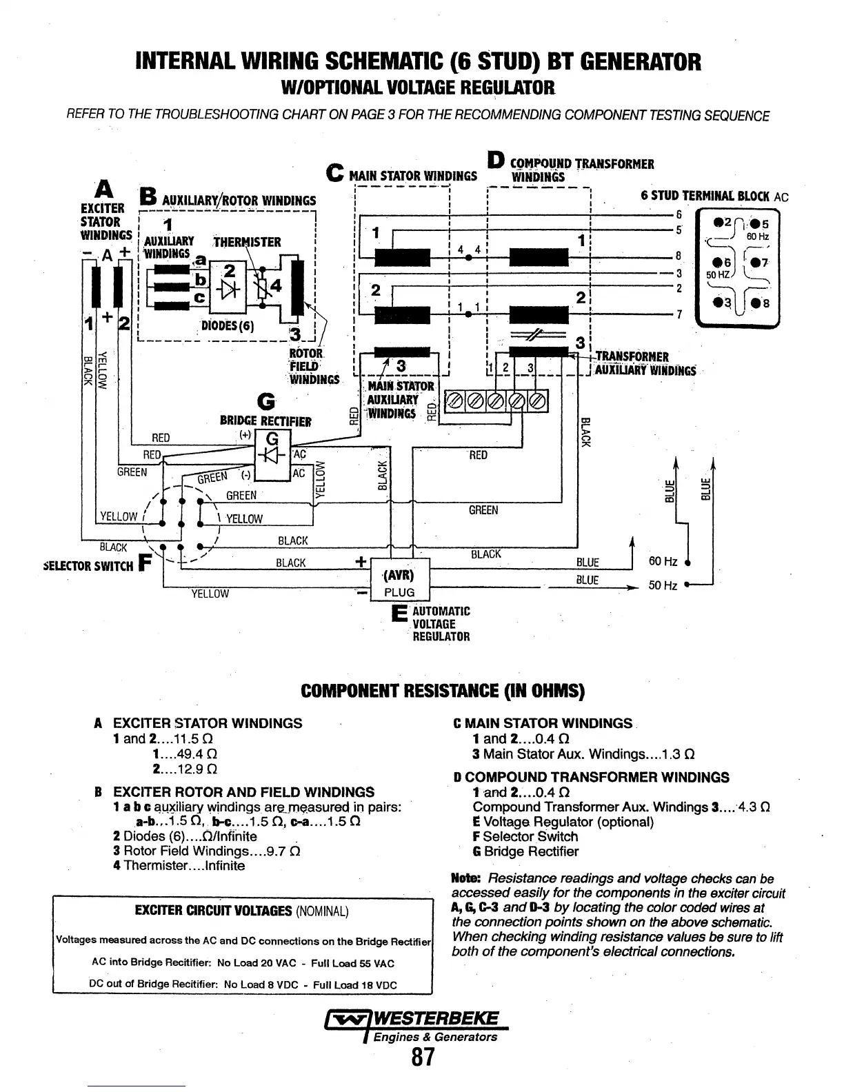
INTERNAL
WIRING
SCHEMAnC
(&
STUD)
BT
GENERATOR
W/OPTIONAL
VOLTAGE
REGUWOR
REFER
TO
THE
TROUBLESHOOTING
CHART
ON
PAGE
3
FOR
THE
RECOMMENDING
COMPONENT
TESTING
SEQUENCE
C
. D
COMPoUND
TRANSFORMER
MAIN
STATOR
WINDINGS
WlliDIIiGS
'-
..
i----·--..;.·-i
i-----.----
-.
I : I 6
STUD
TERMINAL
BLOCK
AC
GREEN
"
I
YElLOW
f
I
BLACK
'
\YELLOW
I
1 I l ' .
RED
GREEN
BLACK
BLACK
BLACK
+
r--4---..__,
BLUE
..__
___
__::;=;.:__--""-1
·(AYR).
1----------...::::Bl~U:::.E
--'
SELECTOR
SWITCH
F
YELLOW
-
PLUG
1-------
__
.....;..;:;___
50
Hz
E'
AUTOMATIC
·
.VOLTAGE
.
•REGULATOR
COMPONENT
RESISTANCE
(IN
OHMS)
A EXCITER
STATOR
WINDINGS
1 and 2 .... 11.5 0
1 ... .49.4 0
2 ....
12.90
B EXCITER
ROTOR
AND FIELD WINDINGS
1 a b c
C!!-!>.!:iJiary
windings
are_m~asured
in pairs:
.a-b
... 1.5
0,
b-e .... 1.5
0,
c-a
.... 1.5 0
2 Diodes
(6)
.... 0/lnfiiiite · .
3 Rotor Field Windings .... 9.7
0
4 Thermister ... .Infinite
EXCITER
CIRCUIT
VOLTAGES
(NOMINAL)
Voltages measured across the
AC
and DC connections
on
the
Bridge Rectifier
AC
into
Bridge Recitifier: No Load 20
VAC
- Full Load 55
Y.AC
DC
out of Bridge Recitifier: No Load 8 VDC - Full Load 18
VDC
C MAIN STATOR WINDINGS.
1 and 2 ....
0.40
3 Main Stator Aux. Windings .... 1.3 0
D COMPOUND TRANSFORMER WINDINGS
1 and
2:
... 0.4 n
Compound Transformer Aux. Windings 3 ...
."4.3
Q
E Voltage Regulator (optional)
F
Selector
Switch
G Bridge Rectifier
Rote: Resistance readings
and
voltage checks can be
accessed easily
for
the components in the exciter circuit
A,
G,
C-3
and
D-3
by
locating the color coded wires
at
the connection
points
shown
on
the above schematic.
When checking winding resistance values
be sure
to
lift
both
of
the component's electrical connections.
Engines & Generators
87