TESTING
EXCITER
.ROTOR
WINDINGS
REFER
TO
THE
WIRING
SCHEMATICS
TROUBLESHOOTING
GUIDES
AND
COMPONENT
RESISTANCE
CHARTS
IN·THIS
MANUAL
B
AUXIUARY
ROTOR
WINDINGS
.-
..
~----;
1
:1·.
i
I I
I .
...
N:
J
ROTOR
AELD
I
-yr
WINDINGS
I · l
L
.::L-:::..
. ...... 1
..
L---·~-
-------
--~
1'ESnll
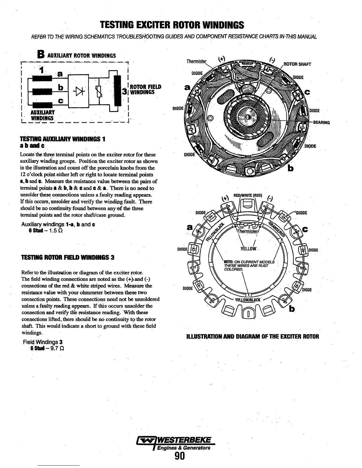
AUXIUARY
WINDINGS
1
abandc
Locate.
the
~terminal
points on the exciter rotor for these
auxiliary
winding groups. Position the exciter rotor as shown
in
the illustration and count
off
the porcelain knobs from the
12
o'clock point either left
or
right to locate tenniri.al points
I,
band
c.
Mea8ure
the resistanCe value between the pairs
of
tenninal points a &
b,
b & c
and
c &
a.
There is no need to
unsolder
th~
connections unless a faulty reading appears.
If
this
occurs,"
tinsolder and verify the winding fault. There
should
be
no continuity found between any•m the three
tenninal points and the rotor shaft/case ground.
Auxiliary
windings
1-a,
b
and
c
&Stud-1.50
TES'DNI
ROTOR
FIELD
WINDINGS
3
Refer to the illustation
or
diagram
of
the exCiter
.~r.
The
field
winding cminections are noted as the
(+")iand
(-)
connections
of
the
red_&
white
striP.ed
wires.
M~itte
the
resistance
value with your ohmmeter between theSe two
connection points. These
connections need not be unsoldered
unless
a faulty reading appears.
If
this occurs unsolder the
connection and verify
tlle
resistance reading. ·With
these
connections lifted, there
Should
be
oo
continuitY.
tQ
the rotor
shaft. This
would
indicate a short to ground with these field
windings.
.
Field
Windings
3
· ··stlld-9.7 a
ILLUSTRAnON-AND
DIAGRAM
OF
THE
EXCITER
ROTOR
l"''IY'lWESTERBEKE
l Engines & Generators
90