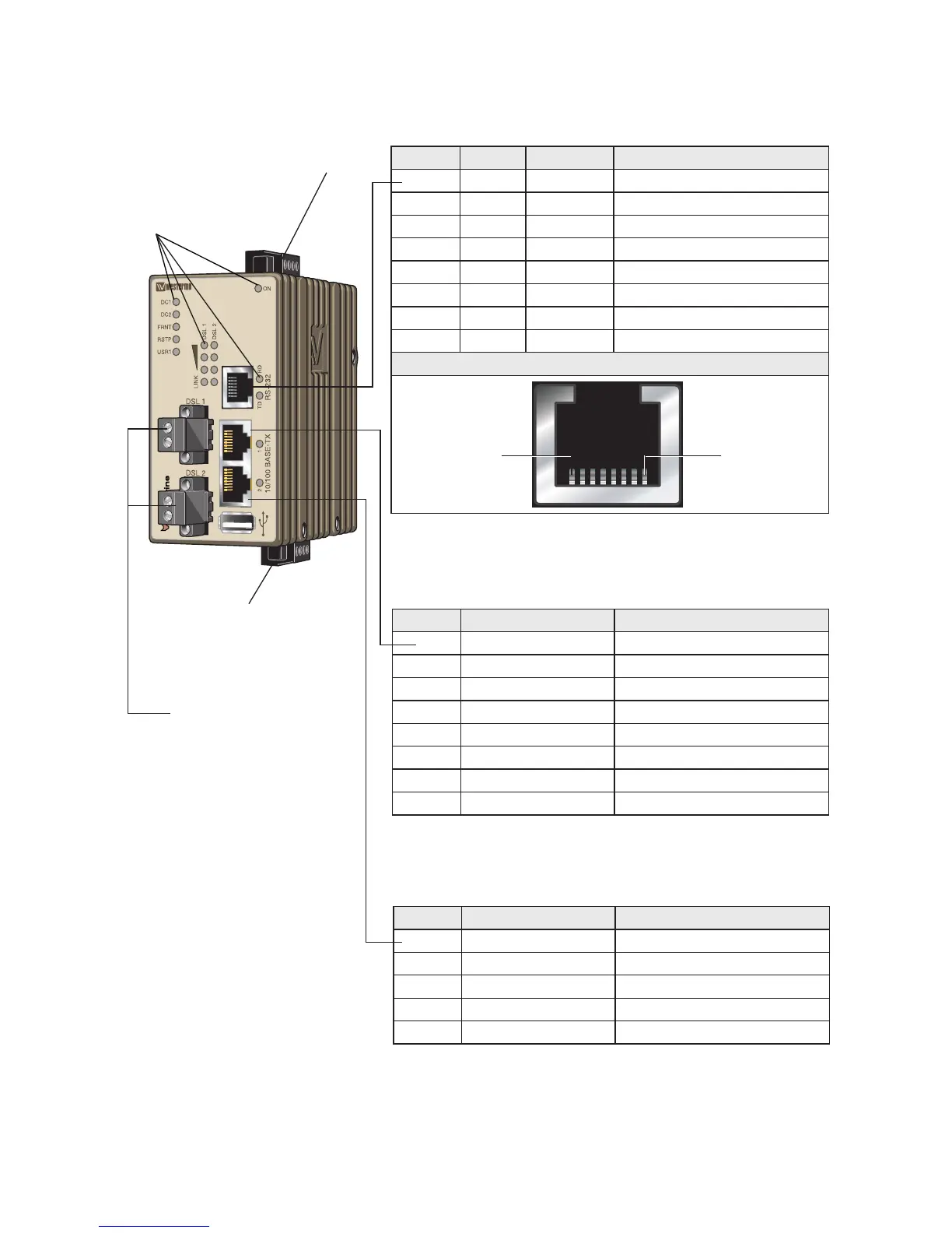
Location of interface ports and LED’s
LED Indicators
Power connection
I/O connection
SHDSL connection
RS-232 Connection
Position Signal Direction* Description
No. 1 DSR Out Data Set Ready
No. 2 DCD Out Data Carrier Detect
No. 3 DTR In Data Terminal Ready
No. 4 SG – Signal Ground, not chassis ground
No. 5 RD
Out
Receive Data
No. 6
TD
In Transmit Data
No. 7 CTS Out Clear To Send
No. 8 RTS In Request To Send
Female
Pin 1Pin 8
* Direction relative this unit.
Ethernet connection TX (2 ports)
Position Direction* Description
No.1 In/Out Transmitted/Received data
No. 2 In/Out Transmitted/Received data
No. 3 In/Out Transmitted/Received data
No. 4 Not Connected
No. 5 Not Connected
No. 6 In/Out Transmitted/Received data
No. 7 Not Connected
No. 8 Not Connected
* Direction relative this unit.
USB
Position Direction* Description
No.1 Out VBUS
No. 2 In/Out D–
No. 3 In/Out D+
No. 4 Out GND
Shield In/Out Connected to protective earth
* Direction relative this unit.