Instructions
English
Thank you for purchasing a Wetrok Duomatic
C-model. Please take time to read and under-
stand these operating instructions before
using your machine. They contain all the infor-
mation required for proper and safe operation
of the machine for its intended use as well as
for maintenance of your Wetrok Duomatic
C43/C50/C60. These instructions must at all
times be readily available to the operator. The
fold-out page contains photos to which the
machine description refers, as well as the
most important technical data for all models.
Table of contents:
1. Responsibility
2. Machine description
3. Safety regulations and accident preven-
tion notes
4. Application, operation and work method
5. Maintenance and cleaning
6. Troubleshooting
7. Service
8. Storage and transport
9. Technical improvements
10. Disposal
11. Warranty
1. Responsibility
The operator of the business is responsible for
the following:
– all users have read and understood the
operating instructions before working with
the machine
– all users understand the safety instructions
and are aware of their importance
– all users have undergone product-specific
training in the application/handling of the
machine
– the users and the way they handle the ma-
chine are periodically supervised and chec-
ked
– the machine is only used by those persons
who have been given express instructions
to do so
– the recognised rules for workplace safety
and accident prevention are complied with
– any further-reaching regulations, prescribed
by authorities or company-internal directi-
ves, are adhered to
– the responsibilities for operating, maintai-
ning and repairing the machine are clearly
defined and followed
– any malfunctions and or damage are/is im-
mediately reported to the service office
1.1 Intended use
– This machine is designed for commercial
cleaning of hard floor surfaces indoors, ta-
king into account these operating instruc-
tions
– The machine must not be used or stored
outdoors in wet conditions
– Use only consumables and accessories re-
commended by Wetrok
– Instructions for safe operation and mainte-
nance are provided in this manual and must
be strictly observed at all times.
1.2 Use other than intended use
–
Any operation of the machine in anything ot-
her than full working condition, or any opera-
tion without due regard to the following safe-
ty instructions and safety notes is prohibited
– Protective devices must not be dismantled
or bypassed
– Product modifications and alterations are
prohibited without express prior written ap-
proval by Wetrok
– Any damage arising from failure to observe
these operating instructions, in particular
Chapters 2, 3, 4 and 5, as well as from im-
proper use or use other than intended use
renders the warranty null and void. Wetrok
declines any liability for consequential da-
mage arising therefrom.
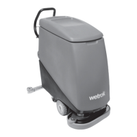
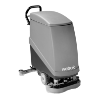
2. Machine description
I. Machine details
A1 Tank lid
A2 Tank
A3 Chassis
A4 Guide drawbar
A5 Brush housing
A6 Fender roller
A7 Splash- and impact protection
A8 Drive wheel (BMA version)
A9 Steering roller
A10 Suction nozzle
A11 Nozzle fender roller
A12 Discharge hose for dirty-water tank
A13 Discharge hose for freshwater tank
A14 Nozzle lowering lever
A15 Suction hose for dirty water
A16 Support wheel for the suction nozzle
A17 Unlocking mechanism – access to the
motor space
B1 Main key-operated switch
B2 Water dosage rate EM- and BM version
B3 Overload indicator reset – LED red
B4 Battery charge state – LED red
B5 Battery charge state – LED yellow
B6 Battery charge state – LED green
B7 Foam monitor – LED red
C1 Regulating screw for nozzle
positioning angle
C2 Regulating screw for nozzle
height adjustment
C3 Nozzle attachment screws
C4 Suction nozzle
C5 Clamping spring
C6 Suction lip
C7 Brush lowering pedal
C8 Emergency Off and battery
charge connector
D1 Battery charge connector
D2 Consumer plug-in connection
D3 Water dosage rate E- and B versions
E1 Solid-wall tank
E2 Dirty-water inlet
E3 Freshwater filter
E4 Dirty-water outlet
E5 Freshwater outlet
E6 Slosh baffle
E7 Suction fitting of the suction turbine
E8 Filter for the suction fitting
E9 Foam generation sensor
F1 Membrane tank
F2 Dirty-water inlet
F3 Membrane
F4 Freshwater filter
F5 Membrane bag suspension strap
F6 Seal for the suction fitting
F7 Filter for the suction fitting
F8 Suction fitting of the suction turbine
F9 Foam generation sensor
G1 Set of 24 V batteries
G2 Brush motor
G3 Freshwater pump
G4 Preliminary filter
G5 Self-drive setting
G6 Safety support
G7 Hour counter
A-models:
H1 Operator console
H2 Main key-operated switch
H3 Drive activation lever (forward/reverse)
H4 Water dosing device
H5 Overload indicator reset – LED red
M-models:
I1 Membrane bag suspension-strap
I2 Membrane bag seal
II. Accessories/consumables:
K1 Polishing brush Union
K2 Scrubbing brush super nylon
K3 Pad drive disc
K4 Polypad (yellow, red, green, black)
K5 Microsol fibre pad
3. Safety regulations and accident
prevention notes
The machine has been constructed according
to the state of the art and according to recog-
nised safety-technology principles. It has
been electrically approved and conforms to
European safety standards (CE). The machine
has several circuit breaker switches, which
serve as protective devices. Nevertheless, ha-
zards can arise, in particular with use other
than intended use, or with failure to observe
the safety instructions or directions given in
the operating instructions.
3.1 Sources of hazards in E models
Electrical voltage/current –
Danger: life-threatening hazard
– Do not use the machine unless the mains
supply cable is in impeccable condition
– In the case of E models, before any work on
electrical installations is carried out, discon-
nect the machine from the mains and pull
out the battery charge connector (D1)
–
Do not jam or damage the mains supply cable
– There is a danger of the cable becoming
entangled because of contact with the rota-
ting brushes
26
 Loading...