Flaperon /Pitch
Parts Description & Operation Instruction
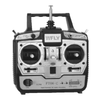
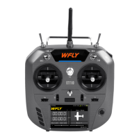
FT06-A Transmitter Features (Front)
1 AIL Aileron Channel 1
2 ELE Elevator Channel 2
3 THR Throttle Channel 3
4 RUD Rudder Channel 4
5 GYR Landing Gear/Gyro Channel 5
6 PIT Channel 6
.: ( )
.: ( )
.: ( )
.: ( )
.: ( )
.: )
Flaperon /Pitch
(
{
Elevator Trim
Power Light
Antenna
Landing Gear/Gyro Switch
Neckstrap
Attachment
Power Trim
Aileron/Throttle
Control Rod
Aileron Trim
Power Switch
Crystal
Rudder Trim
Elevator/Rudder
Control Rod
Handle
Crystal Jack
Battery Cover
Charge Jack
PC Simulator Jack
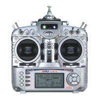
FT06 Transmitter Features (Rear)
FT06 Side of Radio
Underside of Transmitter
Coupling Ways of Receiver
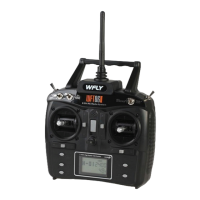
FT06 R/C System
User Manual
FT06 R/C System
User Manual
4
3
()9.6V,<200mA
+
-
(When using the simulator, pull out the TX.)
1 AIL Aileron (Channel 1)----------------
2 ELE Elevator (Channel 2)------------
3 THR Throttle (Channel 3)--------------
4 RUD Rudder (Channel 4)-----------
5 GYR Landing Gear/Gyro (Channel 5)
6 PIT Flaperon/Pitch (Channel 6--------
.:
.:
.:
.:
.:
.:
FRP06 Six Channels Single Conversion Receiver (PPM)
WFR09-P Eight Channels Dual Conversion Receiver (PPM)
72MHz, pull up
the switch to A,
the receiver is
compatible with
WFLY and FUTABA
series transmitters.
Pull down the switch
to B, the receiver is
compatible with JR
series transmiters.
35MHz and 40MHz
are compatible with
FUTABA under JR
transmitters(PPM).
1 AIL ----------------
2 ELE ---------------
3 THR ---------------
4 RUD ------------
5 GYR ---
6 PIT -----------
.:
.:
.:
.:
.:
.:
Aileron (Channel 1)
Elevator (Channel 2)
Throttle (Channel 3)
Rudder (Channel 4)
Landing Gear/Gyro (Channel 5)
Flaperon/Pitch (Channel 6)
7 AUX1 Auxiliary channel 1 (Channel 7)--------
8
.:
.: 2AUX2 Auxiliary channel (Channel 7)--------
9 Power Input 5V.:+
(There are 9 rows needles, 3 needles in each row,
from the top needle to the bottom, the 3 needles are PPM pulse, +5V and Ground.)
MANUAL-V2