4
8.ii Location
• Locate the Water Heater as close to the power supply as possible.
• Locate the heater in a dry location away from the bilge area and standing water.
• Do not install the Water Heater on its side or upside down.
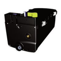
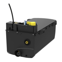
8.iii Mounting Instructions
• Mount this product on a flat, horizontal surface only.
Step 1 Secure mounting brackets to structure with eight #12 minimum screws or ¼” (6.3mm) screws and nuts (See
figure 1.). The minimum mounting surface depth is ½” (12.5mm).
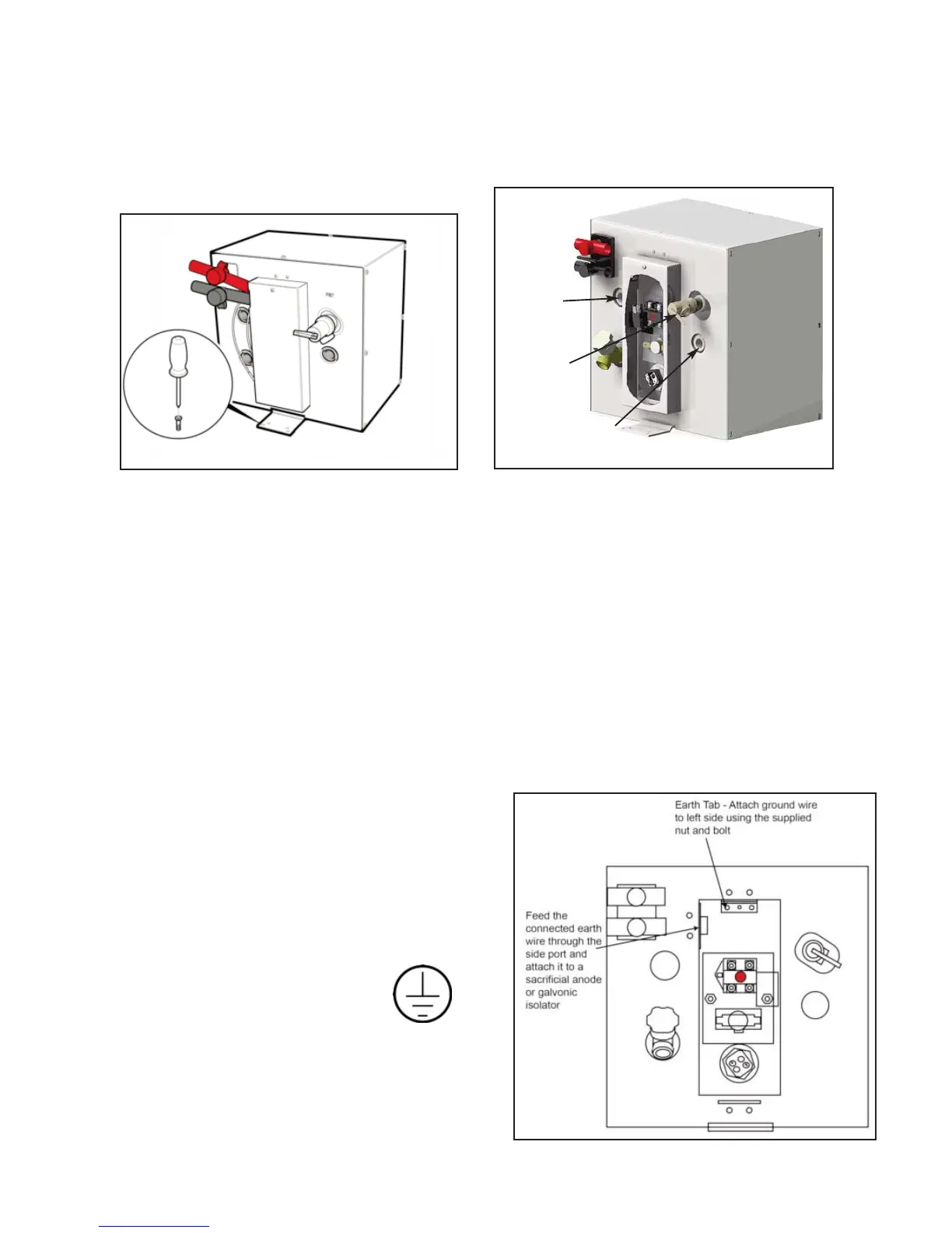
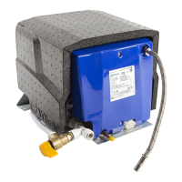
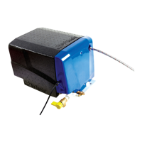
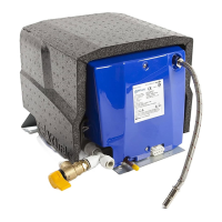
Step 2 Connect the cold water supply and hot water outlet to heater (see figure 2) using ½” N.P.T. fittings or
WX1514 / WX1524B for a Whale
® Quick Connect system.
NOTE: Whale
® recommends the use of a metal Braided Hose Connector on the hot outlet for connection to standard
flexible pipework.
Step 3 The Temperature and Pressure Relief Valve (provided with tubing) must be oriented so that discharge can exit
no more than 6” (152.3mm) above, or at any distance below the structural floor. This must not be in contact
with any live electrical part.
The Temperature and Pressure Relief Valve is factory installed. The pressure relief limits the pressure to 75 psi
(5 bar) +/- 10% and the temperature to 210ºF / 99ºC +/- 10%. For replacement parts see Maintenance
(Section 10) or contact Whale
® Support.
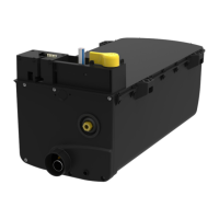
8.iv Grounding Instructions - Aluminium Boats
NOTE For aluminium boats the earth of the water heater must
be connected to a separate sacrificial anode or galvonic
isolator.
NOTE Do not connect the earth wire to the negative of the 12 V
circuit.
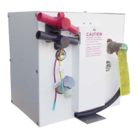
Step 1 Remove the electrical access panel to gain access to the
earth tab. This is located at the top of the internal panel
and labelled with the earth symbol (see figure 3).
Earth Symbol:
Step 2 The separate ground / bonding strip must be connected
to the water heater using the supplied green and yellow
wire. The connection is made to the internal earth tab
using the bolt and nut supplied.
NOTE: Do not place a switch in the grounding circuit.
Figure 1 - Mounting the Water Heater
Cold Water Inlet
Hot Water
Outlet
Figure 2 - Hot and Cold Ports
Temperature
and Pressure
Valve
Figure 3 -
Grounding
Instructions