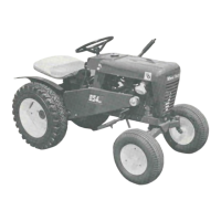
This document is an owner's manual for the Wheel Horse Workhorse "700" tractor, specifically models 1-3745 and 1-3741. It covers lawn and garden tractors manufactured by Wheel-Horse Products, Inc., located in South Bend, Indiana. The manual provides detailed information on assembly, operation, maintenance, and parts for these tractor models.
Function Description
The Wheel Horse Workhorse "700" is a lawn and garden tractor designed for various tasks around a property, including mowing, tilling, and other garden work. It is a versatile machine capable of handling different attachments to suit various needs. The tractor is powered by an engine and features a manual transmission for controlling speed and direction.
Important Technical Specifications
The manual includes a "Specifications" section (page 12) detailing several key technical aspects of the tractor:
- Engine Horsepower (Engine Mfgr's Rating): 7 H.P.
- Engine Crankcase Oil Capacity: 25 oz.
- Fuel Capacity: 4 quarts
- Tires:
- Front: 4.00-8 pneumatic (16" wheel dia.)
- Rear: 6.00-12 pneumatic (22" wheel dia.)
- Speeds: 3 forward to 8 mph, 1 reverse to 2½ mph.
- Turning Radius (to outside wheel): 61 inches
- Overall Length: 61 inches
- Wheelbase: 41½ inches
- Overall Width: 34 inches
- Width at Front Wheels: 33½ inches
- Height: 37½ inches
- Height to Top of Hood: 33½ inches
- Approx. Shipping Weight: 400 lbs.
- Crop Clearance: 7½ inches
- Frame Clearance: 13½ inches
The transmission is a 5053 model, and a detailed parts list for it is provided on page 12. The electrical system includes a 12-volt battery and a 15-amp, 10-minute or 7-amp, 30-minute boost charge for the battery.
Usage Features
The manual outlines various usage features and operational instructions:
-
Starting Engine:
- Fill the gas tank with regular gasoline.
- Open the fuel valve.
- Place the gear shift lever in neutral and apply the parking brake.
- Pull the throttle lever ¾ way out and turn the right lock to its position. The throttle control has a locking device that must be turned to the desired position and locked.
- Pull the choke lever all the way out to choke the engine. If the engine is warm and has been running, choking may not be necessary.
- The Model 1-3745 has a key starter-switch. Turn the key all the way to the start position.
- The Model 1-3741 has a recoil starter with an off and on switch. To start, flip the switch to on and pull the recoil starter. (Note: Keep feet clear of mower while pulling the recoil starter!)
- When the engine starts, push the choke in to off position and regulate the throttle control by turning to the left to unlock and push in or out to the desired speed.
- Depress the clutch pedal all the way to the floor before selecting the desired gear range.
- When starting the tractor in winter, it is desirable to depress the clutch so the engine does not have to turn the transmission.
-
Clutching:
- The gear shift lever should not be forced if the gears do not immediately mesh. Depress the clutch pedal all the way down and let up, then depress again and shift. To avoid sudden starts, release the clutch pedal slowly. While in motion, do not shift gears without depressing the clutch pedal.
- The clutch pedal also operates the brakes when depressed all the way down. For this reason, the operator should depress the pedal only part of the way down when shifting while in motion. This clutch-brake pedal combination makes clutching automatic and applies the brakes to stop.
-
Parking Brake:
- The parking brake is located on the left side of the tractor, as shown in Figure 2. To set the parking brake, depress the clutch-brake pedal as far as possible and push the parking brake down. To release the brake, depress the clutch-brake pedal.
-
Attaching Tools:
- The manual provides complete information on the assembly, attachment, operation, and service of the many attaching tools.
- All lawn implements attach in seconds. Simply lift the tractor hitch pin, insert the tongue, and replace the pin.
- All power implements use the attachment clutch pedal located on the right side of the tractor.
-
Steering & Wheel Assembly: An exploded view (page 5) illustrates the components of the steering and wheel assembly, including the steering wheel, shaft, and front wheel components.
-
Main Frame, Fender & Hood Assembly: An exploded view (page 6) shows the main frame, fender, and hood components. Another exploded view (page 7) details the seat, battery, and other related parts.
-
Transmission: An exploded view (page 11) illustrates the components of the 5053 transmission, along with a detailed parts list (page 12).
Maintenance Features
The manual emphasizes regular maintenance to ensure the longevity and proper functioning of the tractor:
-
Before You Start:
- Check the oil level every 5 operating hours or each time the equipment is used.
- Change the oil every 25 operating hours or sooner if the equipment is operated in extremely dusty or dirty conditions. Refer to the Engine Manual for specific oil recommendations.
- Lubricate all grease fittings with a regular pressure gun lubricant every eight (8) hours of operation. Refer to Figure 1 for the location of grease fittings.
- A light machine oil should be used on all moving parts to keep joints from wearing and squeaking.
- Remove the filter plug, located on the left rear side of the transmission, and fill to level of hole with a good grade of S.A.E. 90 oil (will require about 3 pints).
- The transmission oil level should be checked after every 40 hours of use. The transmission should be drained once a year by removing the plug on the bottom to drain oil. Refill as above through the top. This is a regular automotive type transmission with sliding gears and should have the same care as your car.
-
Battery:
- The battery installed in the tractor is a dry charged battery. It is important to properly prepare this battery to ensure good service and long life.
- Remove vent caps. Remove or destroy any seal-ing device which may have been used to close or restrict the vent openings.
- Fill each cell of the battery to the proper level with the battery electrolyte.
- NOTE: Temperature of battery and electrolyte at time of filling should be above 60°F. Never fill battery in the vehicle.
- BOOST CHARGE: 15 amps for 10 minutes or 7 amps for 30 minutes. Adjust electrolyte level, if necessary, after charging.
- Install the battery with the battery toward the rear of the tractor. Start the engine. If the battery has been in service, add only approved water.
- DO NOT ADD ACID.
-
Tires:
- The front tires are 4.00/4.00-8 and should be inflated to 12 pounds of air pressure. The rear tires are 6 x 12 and should have 8 pounds of air pressure. The tires can also be filled with ballast if desired. Ordinarily, this is not necessary as the weight of the operator will add sufficient weight for adequate traction.
-
Care of Tractor:
- Keep the tractor greased and oiled regularly. Refer to Figure 1 for the location of grease fittings. Check transmission and engine case oil levels.
- Keep the engine air cleaner clean. This will add to engine life.
- Keep tires properly inflated. See previous instructions.
- Keep the tractor covered and in a dry place when not in use.
- Keep grass and dirt out of the engine cowling as these will stop the flow of air and decrease engine life.
- BRAKE ADJUSTMENT: The brake band, located on the left side of the transmission, brakes the transmission and in turn stops the wheels.
- CLUTCH-BRAKE PEDAL ADJUSTMENT: The clutch-brake pedal rod may be turned in or out to adjust the pedal to the operator's desired position. Remove the pin from the rod and turn in or out for adjustment. There are also two holes in the pedal to adjust the travel. The upper hole is for a short movement of travel, the lower hole is for a long movement.
- When replacing belts, be sure to purchase genuine Wheel Horse belts, as these belts are specifically designed for each application. (NOTE: Make sure all pulleys are in line.)
- To raise the seat/fender unit, pull the knob back. See Figure 1. The seat should be latched before operating the tractor.
The manual also includes a "Safety Suggestions" section (page 3) that provides important guidelines for safe operation and maintenance of the tractor.