P81960 J
Sheet 3 of 4
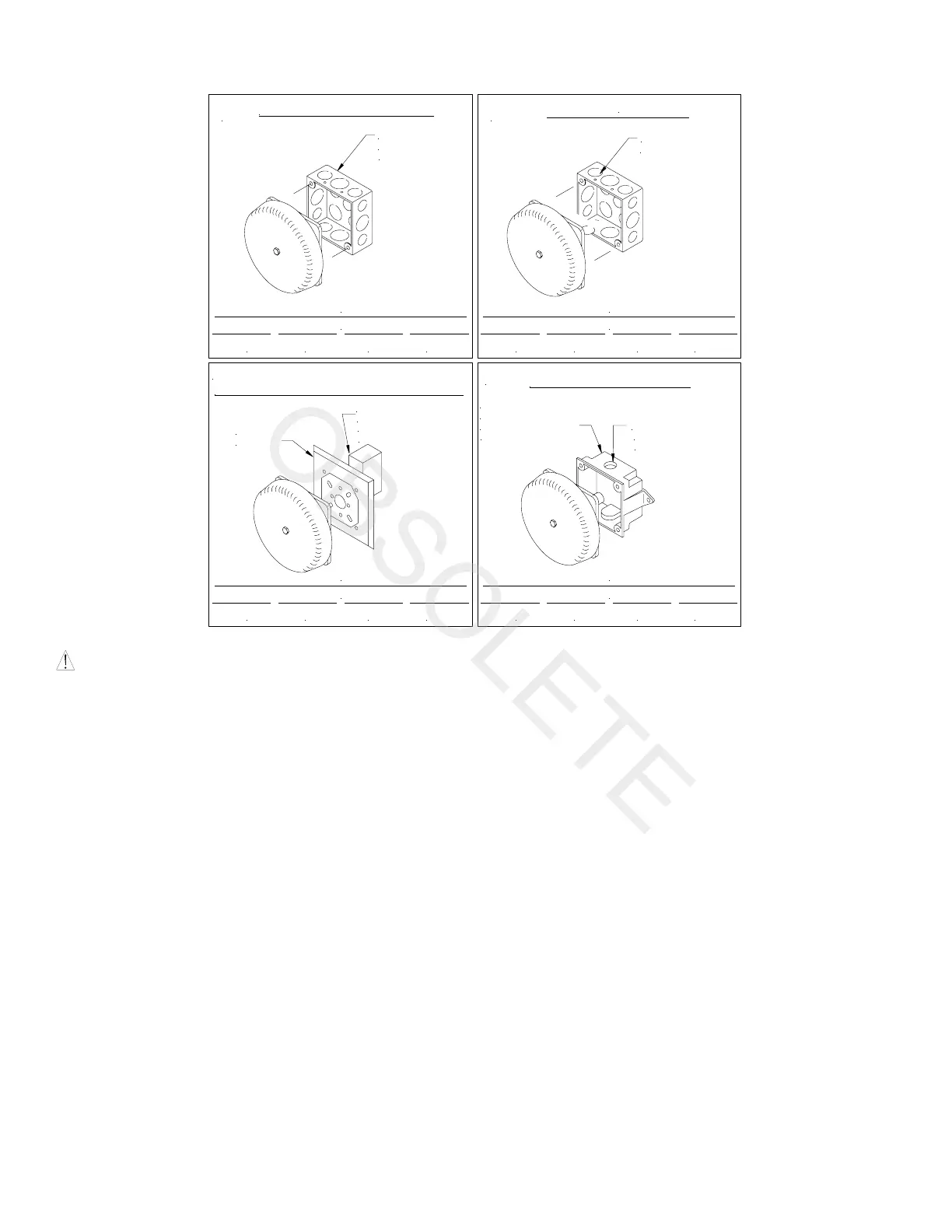
MOUNTING OPTIONS: (Mounting Plates and backboxes ordered separately - specify color)
A
SEMI-FLUSH MOUNTING
STANDARD
4" SQUARE
BACKBOX
AWG #18 AWG #16 AWG #14 AWG #12
MAXIMUM NUMBER OF CONDUCTORS
4 4 4
4
B
AWG #18 AWG #16 AWG #14 AWG #12
MAXIMUM NUMBER OF CONDUCTORS
4 4 4 4
STANDARD
BACKBOX
SURFACE MOUNTING
C
CONCEALED CONDUIT MOUNTING
AWG #18 AWG #16 AWG #14 AWG #12
MAXIMUM NUMBER OF CONDUCTORS
4 4 4 4
ADAPTOR
PLATE
EXISTING BOX
IN WALL
(15.0 CUBIC
INCHES MIN.)
D
OUTDOOR MOUNTING
AWG #18 AWG #16 AWG #14 AWG #12
MAXIMUM NUMBER OF CONDUCTORS
4 4 4 4
ENTRANCE
1/2" CONDUIT
MOUNTED ON
BACKBOX TO BE
WEATHER RESISTANT
WALL SURFACE
ON TOP
MOUNTING PROCEDURES:
CAUTION: If sheathed multiconductor cable or 3/4" conduit fittings are used, check that installed product has sufficient clearance
and wiring room prior to installing backboxes and conduit.
1. For weather resistant installation, use outdoor mounting option. Outdoor backbox must be mounted vertically with "TOP" as
marked to allow any moisture or condensation to drain properly through drain holes on bottom of backbox.
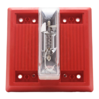
2. Each bell mechanism is adjusted to operate only with the shell provided. Do not mix shells and mechanisms during installation.
Do not readjust bell mechanisms during installation.
3. The polarity shown in the wiring diagram is for the proper operation of the signals.
4. Inrush current of all bells is approximately 4 times rated current. This inrush current surge exists for about 0.006 seconds and
must be supplied by the system power supply to insure start-up of all devices. If the system power supply does not have
sufficient surge capability (generally provided by large filter capacitors), loading of the supply should be based on the DC bell
inrush requirements rather than on their rated (steady-state) current. Make sure the system power supply is compatible with the
specified inrush current.
5. All bells will operate on full-wave-rectified (unfiltered) DC as well as pure (filtered) DC. Motor Bells will operate over a
voltage range of: 6VDC = 4.2-7.8VDC; 12VDC = 8-17.5VDC; 24VDC = 16-33VDC. Operate only within specified voltage
range for rated performance and endurance. Performance ratings are based on nominal input voltage.
6. All bells will operate on "coded systems" up to 2 on-off cycles per second
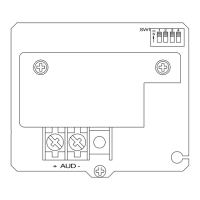
7. Each input terminal accepts (2) leads for in-out wiring of 12-22 AWG wire. Break wire run to provide electrical supervision.
Strip leads approximately 3/8" for connection to terminals.
8. Select largest backbox shown in Mounting Options where possible, to provide additional wiring room for easy installation.
9. Conduit entrance to backboxes should be selected to insure sufficient wiring clearance for installed equipment. When extension
rings are required, conduit should enter through backbox, not extension ring. Use Steel City #53151/1-1/2" deep or #53171/2-
1/8" deep extension rings or equal with same area cut out in back.
10. Anechoic dB ratings are "free field" (anechoic) conditions. Typical indoor sound output is usually higher than rated anechoic
dB.
 Loading...