EasyManua.ls Logo

Wheelock MT-24-LSM User Manual

Default Icon
9 pages
To Next Page IconTo Next Page
Page #1 background imageLoading...
Page #1 background image
P82475 K
Sheet 1 of 9
273 Branchport Avenue
Long Branch, NJ 07740 Thank you for using our products.
(800) 631-2148
INSTALLATION INSTRUCTIONS
www.wheelockinc.com
MULTITONE STROBE APPLIANCES
Use this product according to this instruction manual. Please keep this instruction manual for future reference.
GENERAL:
The Multitone Strobe Appliances are UL Listed under Standard 1971 for Emergency Devices for the Hearing Impaired and UL
Standard 464 for Audible Signal Appliances. The LSM strobes are listed at 15 candela under UL Standard 1971 and meet 75 candela
intensity on axis with low current draw. They are listed for indoor use with the backboxes specified in these instructions (See
Mounting Options). Models with LS, MS and IS strobes are Listed for wall or ceiling mounting; models with LSM strobes are Listed
for wall mounting. The Multitone Strobe Appliances use a Xenon flashtube with solid state circuitry enclosed in a rugged Lexan
lens to provide maximum visibility and reliability for effective visible signaling.
Multitone Strobe Appliances can be field set to produce any one of eight commonly used alarm tones. Sound output can be field set
to provide either HIGH (HI) dBA or STANDARD (STD) dBA sound output level.
All Multitone Strobe models are designed for use with either filtered DC or unfiltered Full-Wave-Rectified (FWR) input voltage. The
Multitone Strobe Appliances have separate input terminals for alarm tone activation and strobe activation. Shunt wires are provided
to operate both the alarm tone and the strobe simultaneously on a single input circuit (See Wiring Diagram). All inputs are polarized
for compatibility with standard reverse polarity supervision of circuit wiring by a Fire Alarm Control Panel (FACP).
NOTE
: All
CAUTIONS
and
WARNINGS
are identified by the symbol
. All warnings are printed in bold capital letters.
WARNING: PLEASE READ THESE INSTRUCTIONS CAREFULLY BEFORE USING THIS PRODUCT. FAILURE TO COMPLY
WITH ANY OF THE FOLLOWING INSTRUCTIONS, CAUTIONS AND WARNINGS COULD RESULT IN IMPROPER
APPLICATION, INSTALLATION AND/OR OPERATION OF THESE PRODUCTS IN AN EMERGENCY SITUATION, WHICH
COULD RESULT IN PROPERTY DAMAGE AND SERIOUS INJURY OR DEATH TO YOU AND/OR OTHERS.
WARNING: THE MULTITONE STROBE APPLIANCES MUST BE FIELD SET TO THE DESIRED dBA SOUND OUTPUT LEVEL
AND ALARM TONE BEFORE THEY ARE INSTALLED. THIS IS DONE BY PROPERLY INSERTING A JUMPER PLUG AND
ADJUSTING A FOUR POSITION SWITCH IN ACCORDANCE WITH THESE INSTRUCTIONS. INCORRECT SETTINGS WILL
RESULT IN IMPROPER PERFORMANCE AND MAY DAMAGE THE PRODUCT, WHICH COULD RESULT IN PROPERTY
DAMAGE AND SERIOUS INJURY OR DEATH TO YOU AND/OR OTHERS.
SPECIFICATIONS
:
Table 1: UL Listed Models
Model
Nominal
Voltage
(VDC)
Rated
Voltage
(VDC)
Strobe
Candela
(CD)
Anechoic
dBA at
10 Feet
Mounting
Options
MT-12-LS 12 10.5-15.6 15 87-99
MT-12-LSM 12 10.5-15.6 15* 87-99
MT-12-MS 12 10.5-15.6 30 87-99
MT-24-LS 24 20.0-31.0 15 87-99 A,B,C,D
MT-24-LSM 24 20.0-31.0 15* 87-99 E,F,G
MT-24-MS 24 20.0-31.0 30 87-99
MT-24-IS 24 20.0-31.0 75 87-99
MT4-12-LS 12 10.5-15.6 15 87-99
MT4-12-LSM 12 10.5-15.6 15* 87-99
MT4-12-MS 12 10.5-15.6 30 87-99
MT4-24-LS 24 20.0-31.0 15 87-99 H
MT4-24-LSM 24 20.0-31.0 15* 87-99
MT4-24-MS 24 20.0-31.0 30 87-99
MT4-24-IS 24 20.0-31.0 75 87-99
*15cd models are Listed at 15cd and meet 75cd on axis
WARNING: CHECK THE MINIMUM AND MAXIMUM OUTPUT OF THE POWER SUPPLY AND STANDBY BATTERY AND
SUBTRACT THE VOLTAGE DROP FROM THE CIRCUIT WIRING RESISTANCE TO DETERMINE THE APPLIED VOLTAGE TO
THE SIGNALING DEVICE.
Copyright 1993-1997, 2000 Wheelock, Inc. All rights reserved.
Question and Answer IconNeed help?

Do you have a question about the Wheelock MT-24-LSM and is the answer not in the manual?

Wheelock MT-24-LSM Specifications

General IconGeneral
Voltage24 VDC
Operating Temperature32°F to 120°F (0°C to 49°C)
Flash Rate1 flash per second
Housing MaterialPlastic
ColorRed
CategoryFire Alarm
TypeNotification Appliance
Sound OutputHorn
TonesMarch Time
Strobe Intensity15 cd
MountingSurface
ComplianceUL

Summary

Product Overview

Product Features and Listings

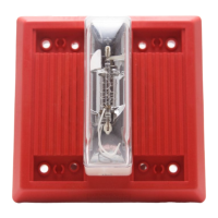
Describes product capabilities, UL standards, and components like Xenon flashtube and input voltage compatibility.

Critical Installation Warnings

Highlights essential safety and setup precautions, including field setting requirements for dBA and tone before installation.

SPECIFICATIONS

UL Listed Model Details

Lists specific models with their voltage, candela intensity, and mounting options as per UL standards.

ELECTRICAL AND SOUND SPECIFICATIONS

Audible Appliance Current Ratings

Details current consumption for various audible tones (Horn, Bell, etc.) across 12VDC and 24VDC.

Sound Output Levels (dBA)

Provides anechoic and reverberant sound pressure levels (dBA) for different tones and voltage settings.

Strobe Current Requirements

Lists average, peak, and inrush current requirements for strobe models (LS, MS, LSM, IS).

Operating Voltage Compliance

Stresses adherence to specified operating voltage limits (80%-110%) for safe and effective system operation.

POWER SUPPLY AND WIRING CONSIDERATIONS

Total System Current Calculation

Guides on calculating total current load, including safety factors, for power supplies and circuits.

Power Source Capacity Warning

Warns against overloading power sources or exceeding fuse ratings, which could cause failure during emergencies.

LIGHT DISTRIBUTION

Horizontal Light Intensity

Shows light output distribution at various horizontal angles for different candela ratings and model types.

LIGHT DISTRIBUTION (Continued)

Vertical Light Intensity

Details light output distribution at various vertical angles for different candela ratings and model types.

MULTITONE SETTINGS AND CONFIGURATION

Flash Rate Specifications

Outlines typical flash rates across different voltage ranges for various models as per ADA guidelines.

Device Configuration Overview

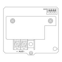
Explains the use of Jumper Plug (DP1) and Switch (SW1) for setting device parameters like dBA and tone.

Default Factory Settings

Lists the pre-configured settings for 12VDC and 24VDC models for dBA output and horn tone.

SETTING DBA SOUND OUTPUT LEVEL

DP1 and SW1 Configuration for dBA

Details how to use DP1 and SW1 to select the desired dBA sound output level (HIGH or STD).

Critical dBA Setting Precautions

Warns about potential unit damage and non-compliance with 75dBA minimum for incorrect dBA settings.

SETTING ALARM TONE

SW1 Switch Settings for Tones

Guides on using SW1 positions 2, 3, 4 to select specific alarm tones like Horn, Bell, Code 3, etc.

Tone Application Guidance

Provides recommendations on using specific tones for fire evacuation signaling or general signaling use.

WIRING INFORMATION AND DIAGRAMS

Independent Strobe/Audible Wiring

Illustrates wiring for separate control of strobe and audible components using terminal blocks.

Unison Strobe/Audible Wiring

Shows wiring for simultaneous operation of strobe and audible components using shunt wires.

MOUNTING OPTIONS AND BACKBOXES

Physical Mounting Configurations

Presents various backbox types (flush, surface, IOB) and mounting methods with diagrams (Figures A-H).

Field Wire Capacity Warning

Alerts users to maximum conductor limits for backboxes to prevent wire stress and potential product damage.

MOUNTING NOTES AND INSTALLATION BEST PRACTICES

Flush and Surface Mounting Details

Explains installation for flush mounts in standard electrical boxes and surface mounts using IOB backboxes.

Retrofit and Conduit Installation

Covers retrofitting to existing boxes and proper conduit entry into backboxes, avoiding extension rings.

Wire Management and Space Optimization

Advises on efficient wire placement and ensuring adequate wiring space within the backbox to prevent stress.

OPERATIONAL SAFETY AND COMPLIANCE

Hearing Hazard from Sound Levels

Warns about sound pressure levels exceeding 120dBA and potential hearing damage from proximity.

Strobe Visibility and Placement

Emphasizes correct strobe placement for effective visual notification and alerting of intended viewers.

Photo-Sensitivity and Flash Rate Concerns

Discusses potential photo-sensitive effects from strobes and recommends flash rate compliance (max 5 Hz).

System Interoperability Checks

Recommends verifying compatibility with other system components and checking their installation guidelines.

LIMITED WARRANTY AND LIABILITY

Warranty Coverage and Period

Details the three-year warranty period from manufacture date and general coverage terms.

Warranty Exclusions and Limitations

Lists conditions not covered, such as software, misuse, unauthorized parts, and liability caps.

Manufacturer Liability Cap

Defines the maximum extent of the manufacturer's responsibility, limited to product price and excluding consequential damages.

Related product manuals