EasyManua.ls Logo

Wheelock MB Series - User Manual

Default Icon
4 pages
Print Icon
To Next Page IconTo Next Page
Loading...
P81960 J
Sheet 1 of 4
273 Branchport Ave.
Long Branch, N.J. 07740
(800) 631-2148 Thank you for using our products.
www.wheelockinc.com
INSTALLATION INSTRUCTIONS
SERIES MB BELLS
Use this product according to this instruction manual. Please keep this instruction manual for future reference.
GENERAL:
Series MB Motor Bells are UL Listed for Fire Protective Service with the exception of the 6VDC Motor Bell which is UL approved
for general signaling use. The Motor Bell Series incorporates a high torque permanent magnet motor to provide high output with
minimum current draw. Integral MOV suppression is provided to minimize RFI and turn-off transients. In-out wiring terminals and a
built-in trim plate, for semi-flush mounting, are provided for easy installation. The Motor Bell Series is available in 6VDC with a 6"
bell shell and 12VDC or 24VDC with either a 6" or 10" bell shell.
NOTE: All CAUTIONS and WARNINGS are identified by the symbol . All warnings are printed in bold capital letters.
WARNING: PLEASE READ THESE INSTRUCTIONS CAREFULLY. FAILURE TO COMPLY WITH ANY OF THE
FOLLOWING INSTRUCTIONS, CAUTIONS AND WARNINGS COULD RESULT IN IMPROPER APPLICATION,
INSTALLATION AND/OR OPERATION OF THESE PRODUCTS IN AN EMERGENCY SITUATION, WHICH COULD
RESULT IN PROPERTY DAMAGE AND SERIOUS INJURY OR DEATH TO YOU AND/OR OTHERS.
SPECIFICATIONS:
Table 1: UL Listed Models and Ratings
Maximum RMS Current Draw Reverberant dBA Per UL 464 Mounting
Model Gong Size
Voltage Range
(VDC/VRMS)
DC FWR Min Nom Max Options
MB-G6-6 6" 4.2-7.8 0.130 0.160 75 82 85 A,B,C,D
MB-G6-12 6" 8.0-17.5 0.090 0.110 79 85 88 A,B,C,D
MB-G10-12 10" 8.0-17.5 0.090 0.110 82 88 91 A,B,C,D
MB-G6-24 6" 16.0-33.0 0.040 0.056 82 85 88 A,B,C,D
MB-G10-24 10" 16.0-33.0 0.040 0.056 82 88 91 A,B,C,D
WARNING: FOR UL APPLICATIONS THESE APPLIANCES WERE TESTED TO THE OPERATING VOLTAGE
LIMITS OF 16-33 VOLTS FOR 24V MODELS, 8-17.5V FOR 12V MODELS, OR 4.2-7.8V FOR 6V MODELS USING
FILTERED (DC) OR UNFILTERED FULL-WAVE-RECTIFIED (FWR). DO NOT APPLY 80% AND 110% OF THESE
VOLTAGE VALUES FOR SYSTEM OPERATION.
WARNING: MAKE SURE THAT THE TOTAL RMS CURRENT REQUIRED BY ALL APPLIANCES THAT ARE CONNECTED
TO THE SYSTEM’S PRIMARY AND SECONDARY POWER SOURCES, NAC CIRCUITS, SM, DSM SYNC MODULES OR
WHEELOCKS POWER SUPPLIES DO NOT EXCEED THE POWER SOURCES’ RATED CAPACITY OR THE CURRENT RATINGS
OF ANY FUSES ON THE CIRCUITS TO WHICH THESE APPLIANCES ARE WIRED. OVERLOADING POWER SOURCES OR
EXCEEDING FUSE RATINGS COULD RESULT IN LOSS OF POWER AND FAILURE TO ALERT OCCUPANTS DURING AN
EMERGENCY, WHICH COULD RESULT IN PROPERTY DAMAGE AND SERIOUS INJURY OR DEATH TO YOU AND/OR
OTHERS.
When calculating the total currents: Use Table 1 to determine the highest value of “RMS Current” for an individual bell (across the
expected operating voltage range of the bell), then multiply these values by the total number of bells; be sure to add the currents for
any other appliances, including audible signaling appliances, powered by the same source and include any required safety factors.
If the peak current exceeds the power supplies’ peak capacity, the output voltage provided by the power supplies may drop below the
listed voltage range of the appliances connected to the supply and the voltage may not recover in some types of power supplies. For
example, an auxiliary power supply that lacks filtering at its output stage (either via lack of capacitance and/or lack of battery backup
across the output) may exhibit this characteristic.
Copyright 2004 Wheelock, Inc. All rights reserved.
OBSOLETE
Question and Answer IconNeed help?

Do you have a question about the Wheelock MB Series and is the answer not in the manual?

Summary

General Product Overview and Safety

Product Description and Safety Warnings

Outlines Series MB Bell features, UL listing, and critical safety warnings for proper use.

Product Specifications and Ratings

UL Listed Models and Performance Data

Details UL listed models, voltage ranges, current draw, sound levels, and mounting options.

Voltage and Current Operational Guidelines

Critical warnings on operating voltage limits and total RMS current for system safety.

Mounting Information and Procedures

Wiring Diagram and Connections

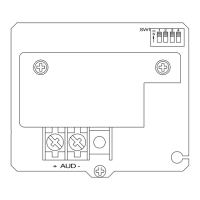
Illustrates the wiring diagram for connecting Series MB Bells.

Bell Shell Mounting Steps

Step-by-step guide for physically attaching the bell shell to the housing.

Mounting Options and Configurations

Details for semi-flush, surface, conduit, and outdoor mounting, including conductor capacity.

Detailed Installation Procedures

Comprehensive instructions for installation, weather resistance, wiring, and operation.

Legal and Warranty Information

Product Use Limitations and Disclaimers

Conditions and restrictions on product use and extracted content.

Limited Warranty Terms

Details of the three-year limited warranty and its exclusions.

Limitation of Liability

Defines Wheelock's liability limits for product claims and damages.

Overview

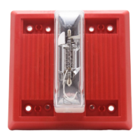
The Wheelock Series MB Motor Bells are UL Listed for Fire Protective Service, with the exception of the 6VDC Motor Bell which is UL approved for general signaling use. These bells are designed to provide high output with minimum current draw, making them suitable for emergency signaling applications.

Function Description:

The Series MB Motor Bells are electromechanical signaling devices that produce an audible alarm. They incorporate a high torque permanent magnet motor to ensure reliable operation and strong sound output. Integral MOV suppression is included to minimize Radio Frequency Interference (RFI) and turn-off transients, which helps maintain system integrity and prevents interference with other electronic equipment. The bells feature in-out wiring terminals and a built-in trim plate for semi-flush mounting, facilitating easy installation.

Important Technical Specifications:

  • Voltage Options:
    • 6VDC with a 6-inch bell shell (MB-G6-6)
    • 12VDC with either a 6-inch (MB-G6-12) or 10-inch (MB-G10-12) bell shell
    • 24VDC with either a 6-inch (MB-G6-24) or 10-inch (MB-G10-24) bell shell
  • Operating Voltage Range (VDC/VRMS):
    • 6V models: 4.2-7.8V
    • 12V models: 8.0-17.5V
    • 24V models: 16.0-33.0V
    • Note: Do not apply 80% and 110% of these voltage values for system operation.
  • Maximum RMS Current Draw (DC/FWR):
    • MB-G6-6: 0.130A (DC), 0.160A (FWR)
    • MB-G6-12/MB-G10-12: 0.090A (DC), 0.110A (FWR)
    • MB-G6-24/MB-G10-24: 0.040A (DC), 0.056A (FWR)
  • Reverberant dBA (Per UL 464):
    • MB-G6-6: 75 (Min), 82 (Nom), 85 (Max)
    • MB-G6-12: 79 (Min), 85 (Nom), 88 (Max)
    • MB-G10-12: 82 (Min), 88 (Nom), 91 (Max)
    • MB-G6-24: 82 (Min), 85 (Nom), 88 (Max)
    • MB-G10-24: 82 (Min), 88 (Nom), 91 (Max)
    • Note: Anechoic dB ratings are "free field" (anechoic) conditions. Typical indoor sound output is usually higher than rated anechoic dB.
  • Power Source Compatibility: All bells will operate on full-wave-rectified (unfiltered) DC as well as pure (filtered) DC.
  • Inrush Current: Approximately 4 times the rated current, lasting for about 0.006 seconds. The system power supply must be capable of supplying this surge to ensure proper device start-up.
  • Wiring: Each input terminal accepts two leads for in-out wiring of 12-22 AWG wire. Leads should be stripped approximately 3/8" for connection. Break wire run to provide electrical supervision.
  • Operating Temperature: Not explicitly stated, but typically designed for indoor fire alarm system environments unless specified for outdoor use.
  • Mounting Options: Semi-flush, surface, concealed conduit, and outdoor mounting. Mounting plates and backboxes are ordered separately.

Usage Features:

  • Easy Installation: The bells come with a built-in trim plate for semi-flush mounting and in-out wiring terminals. Installation involves unscrewing the center bolt to remove the bell shell, connecting wiring, mounting the housing with provided screws, and then replacing the bell shell, ensuring proper alignment with the guide pin.
  • Versatile Mounting: Various mounting options are available to suit different installation requirements, including standard 4" square backboxes for semi-flush and surface mounting, existing boxes for concealed conduit, and weather-resistant backboxes for outdoor use.
  • Coded Systems Compatibility: All bells will operate on "coded systems" up to 2 on-off cycles per second, allowing for different signaling patterns.
  • Polarity: The polarity shown in the wiring diagram must be followed for proper operation of the signals.
  • Outdoor Installation: For weather-resistant installations, the outdoor mounting option requires the backbox to be mounted vertically with the "TOP" marking facing up to allow moisture to drain properly through the drain holes at the bottom.
  • Wiring Clearance: It is crucial to select the largest possible backbox and appropriate conduit entrance to ensure sufficient wiring clearance for the installed equipment. If extension rings are used, conduit should enter through the backbox, not the extension ring.

Maintenance Features:

  • No Readjustment: Each bell mechanism is factory-adjusted to operate only with its provided shell. It is critical not to mix shells and mechanisms from different bells during installation, and not to readjust bell mechanisms.
  • Periodic Testing: As with all notification appliances, the Series MB bells must be periodically tested (at least twice a year or more often) in accordance with local, state, and federal codes, regulations, and laws, as well as the latest National Fire Protection Association (NFPA) guidelines.
  • System Compatibility Check: Before installation, ensure that the total RMS current required by all connected appliances does not exceed the power sources' rated capacity or the current ratings of any fuses. Overloading can lead to system failure during an emergency.
  • Power Supply Compatibility: Verify that the system power supply is compatible with the bell's specified inrush current requirements to ensure reliable start-up of all devices.
  • Limited Warranty: Wheelock products are warranted against mechanical and electrical defects for a period of three years from the date of manufacture. This warranty is void if any part not furnished by Wheelock is installed in the product. Users are responsible for determining product suitability and ensuring proper application, installation, and maintenance.

Wheelock MB Series Specifications

General IconGeneral
BrandWheelock
ModelMB Series
CategoryFire Alarms
LanguageEnglish

Related product manuals