P81960 J
Sheet 2 of 4
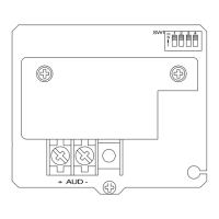
WIRING DIAGRAM:
Figure 1:
FROM PRECEDING
SIGNAL OR FIRE ALARM
CONTROL PANEL (FACP)
+
-
+
-
OR END OF LINE
RESISTOR (EOLR)
TO NEXT BELL
+
-
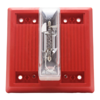
MOUNTING INFORMATION:
Mounting Options Are Shown In The Following Diagrams:
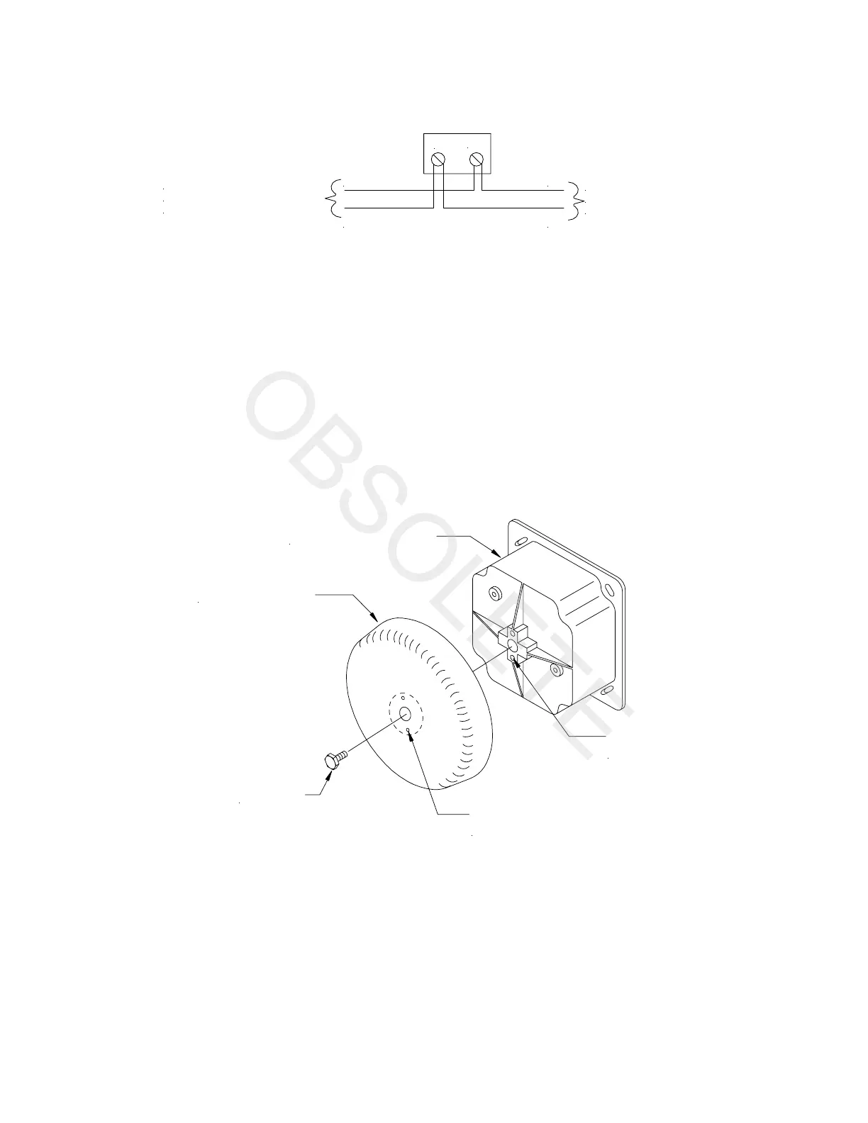
1. Unscrew the center bolt to remove the bell shell. (See Mounting Procedures Note 2 .)
2. Connect wiring as shown in wiring diagram. Note polarity indicated on back cover of housing.
3. Mount housing with screws provided. (Note "TOP" arrow.)
4. Replace bell shell and secure with center bolt. Be sure shell is properly aligned with housing.
Figure 2: Bell Shell Mounting
BELL HOUSING
BELL SHELL
CENTER
BOLT
ALIGN PIN HOLE
WITH GUIDE PIN
GUIDE
PIN
 Loading...