Do you have a question about the Whelen Engineering Company 295SDA1 and is the answer not in the manual?
| Input Voltage | 12 VDC |
|---|---|
| Voltage Range | 10 - 16 VDC |
| Certifications | SAE J1849, California Title 13 |
| Operating Temperature | −30°C to +60°C |
| Outputs | Speaker, Light Control |
| Features | Hands-free operation |
| Dimensions | 2.5 inches |
| Output Power | 100 Watts |
| Current Draw | 8 Amps (average) |
Warning about loud siren noise and the necessity of hearing protection as per OSHA standards.
Essential safety precautions for proper installation and operation to prevent injury or damage.
Guidelines for safe drilling and avoiding air bag deployment areas during installation.
Proper electrical connection to chassis ground and battery for optimal performance.
Whelen Engineering Company Inc. contact information and the Dual Siren Control Center Model 295SDA1.
Overview of siren capabilities including independent amplifiers, protection, and programmable tones.
Summary of lighting control features, including programmable switches and relay outputs.
Instructions for selecting a location and securely mounting the 295SDA1 module using provided hardware.
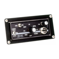
Details on mounting the control head using console brackets or the bail strap mount.
Step-by-step guide for attaching the control head using the bail strap and its mounting holes.
Instructions for routing the control head cable to prevent disconnection or damage.
Information for installing the control head on a Havis Console using a specific mounting kit.
Explanation of wire connections, including power, ground, and speaker wiring for the siren system.
Detailed instructions for connecting the siren power and ground wires to the vehicle battery.
Guide for wiring the siren speakers, including positive and negative connections for each speaker.
Instructions for wiring the horn relay, connecting to the vehicle's horn and horn relay.
Optional connection for two-way radio rebroadcast using two blue wires for external speaker connection.
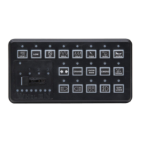
Identification of buttons, switches, and indicators on the 295SDA1 control head for operation.
Explanation of the default behavior of siren buttons like RADIO, WAIL, YELP, TONE3, STANDBY, and MANUAL.
How to use the RADIO button for broadcasting two-way radio signals through the vehicle's loudspeaker.
Description of the synchronized Wail tone produced by the WAIL button.
Description of the synchronized Yelp tone produced by the YELP button.
Explanation of the TONE3 button producing combined Wail and Yelp tones.
How the STANDBY button activates hands-free siren operation via manual or horn ring input.
Description of the MANUAL button producing a phased Wail tone that rises in pitch.
How the AIRHORN button produces different frequency tones on speaker 1 and speaker 2.
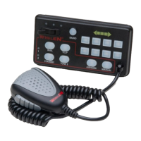
Using the microphone's Push To Talk switch for public address operation on speaker 1.
Explanation of how slide and momentary switches control relay outputs for lighting functions.
Mapping of slide switch positions to specific J2 outputs for controlling lighting and siren functions.
Details on wire colors and switch types for J1 outputs controlled by push-button switches.
Configuration and operation of Traffic Advisor patterns using specific switches.
Explanation of diagnostic indicator LEDs for identifying fault conditions like under/over voltage or short circuits.
Maximum current ratings for various terminals (J1, J2) to ensure safe component connection.
Procedure to configure momentary switches for various types like push-on, momentary, flashing, or TA control.
Steps to configure lighting control switches to activate specific relay outputs or combinations.
Procedure to restore both lighting and siren operations to their original factory default settings.
How to program switches to activate the siren into High Frequency (HF) mode.
How to program switches to deactivate the siren from High Frequency (HF) mode.
Procedure to configure other switches to remotely activate any of the 8 momentary lighting control switches.
Instructions for copying the configuration from one unit to another (primary to secondary).
How to switch between standard and Title 13 operation for airhorn tone behavior.
Procedure to program the unit with a default set of tones that meet Title 13 requirements.
Procedure to adjust the intensity of the red indicator LEDs on the control head.
Procedure to adjust the brightness or dimness of indicator LEDs on the control head.
Procedure to adjust the intensity of the backlight LEDs on the control head.
Procedure to adjust the time the unit operates after the UNIT ENABLE input becomes inactive.
How to change the primary tone for WAIL, YELP, and TONE 3 switch positions for each speaker.
How to change the override tone for WAIL, YELP, and TONE 3 switch positions for each speaker.
List of available tones for Wail, Yelp, Tone 3 buttons and their override tones.
Procedure to change tones for the MANUAL button, affecting speaker 1 and speaker 2.
Procedure to change tones for the HANDS FREE cycle positions activated by the STANDBY switch.
Procedure to change tones for both MANUAL and AIRHORN buttons for speaker 1 and speaker 2.
List of available tones specifically for the AIRHORN button.
Instructions for adjusting the RADIO or PA volume using a small flat blade screwdriver.
Table outlining valid DIP switch settings and their corresponding operations (Normal, Lighting, Siren).