Page 1
©2007 Whelen Engineering Company Inc.
Form No.14157A (081709)
For warranty information regarding this product, visit www.whelen.com/warranty
Automotive: Serial Communications
Installation Guide:
Control Point Module
for WeCan® Lightbars
51 Winthrop Road
Chester, Connecticut 06412-0684
Phone: (860) 526-9504
Internet: www.whelen.com
Sales e-mail: autosale@whelen.com
Customer Service e-mail: custserv@whelen.com
ENGINEERING COMPANY INC.
WARNING: This product can expose you to chemicals including Lead which is known to the State of California to cause cancer and birth defects or
other reproductive harm. For more information go to www.P65Warnings.ca.g
ov.
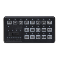
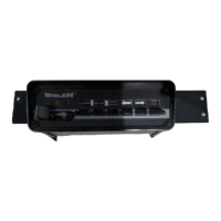
USB
Port
18
9
17
8
16
7
15
6
14
5
13
4
12
3
11
2
10
1
1
4
2
5
3
6
*NOTE: Apply +12VDC to the WHT/GRN
and WHT/YEL wires simultaneously for
split Traffic Advisor.
DEFAULT CONFIGURATION (12V Inputs)
COLOR
GREEN
GRN/WHT
GRN/BLK
WHT/RED
WHITE
YELLOW
WHT/VIO
WHT/GRN
WHT/ORG
BLUE
BLU/WHT
BLU/BLK
WHT/BRN
WHT/BLK
WHT/BLU
RED/WHT
WHT/YEL
VIOLET
*
*
FUNCTION
FRONT PATTERN 1
FRONT PATTERN 2
FRONT PATTERN 3
FRONT PATTERN 4
DRIVER ALLEY
PASSENGER ALLEY
AUX
RIGHT TRAFFIC ADVISOR
CRUISE LIGHTS
REAR PATTERN 1
REAR
REAR
REAR
TAKE DOWNS
FLASHING TAKE DOWN / ALLEY
OVERRIDE
LEFT TRAFFIC ADVISOR
LOW POWER
™
PATTERN 2
PATTERN 3
PATTERN 4
-
-
STEADY
POS
1
2
3
4
5
6
7
8
9
10
11
12
13
14
15
16
17
18
Connect to an ignition controlled
circuit that can accommodate an
additional 250mA load.
from lightbar
1
2
LIGHTBAR CABLE CONNECTOR
2
1
2
2
COLOR
RED
None
BLACK
GREEN
BLK/WHT
GREY
FUNCTION
+12VDC
GROUND
COMM. A
SHIELD
COMM. B
POS
1
2
3
4
5
6
Overview -
The Control Point Module serves as the ‘brains’ of the
Whelen WC Series lightbar. The module is programmed with
the WeCan™ Programming Software via the USB port and in
turn, provides the necessary signals that allow the lightbar to
function in the desired manner.
As represented in the WeCan™ Programming software, each
of the 18 inputs may be programmed to activate any number
or combination of the installed lightbar components. This is
accomplished by applying +12VDC to an input. Refer to the
sample wiring diagrams shown on pgs. 2 through 4, or the
installation guide included with your switches for detailed
wiring information.
Note - The pattern override feature will override all active
LED lightheads with the pattern override flash pattern.
Programming Procedure -
IMPORTANT - It is not necessary to program this device
unless
changes to the default configuration (for example
pattern or switch control changes) are desired.
1. Connect a USB cable from the host PC to the module’s
USB port.
2. Start the WeCan software on the host PC and open the
configuration to be programmed.
3. Click on the “WeCan” button on the menu bar. Select
“Control Point” then “Program” from the fly-out.
4. A window will open to confirm that you are about to
program a Control Point Module. Confirm that the USB
cable is connected to both the module and the PC and
then press “OK” to continue. The software will display a
window when the programming procedure has been
successfully completed.
5. Confirm proper operation of the module.