Installation Manual: GM LT1_A1R13E
Last Updated: February 12th, 2019
Page 18 of 36
www.whipplesuperchargers.com
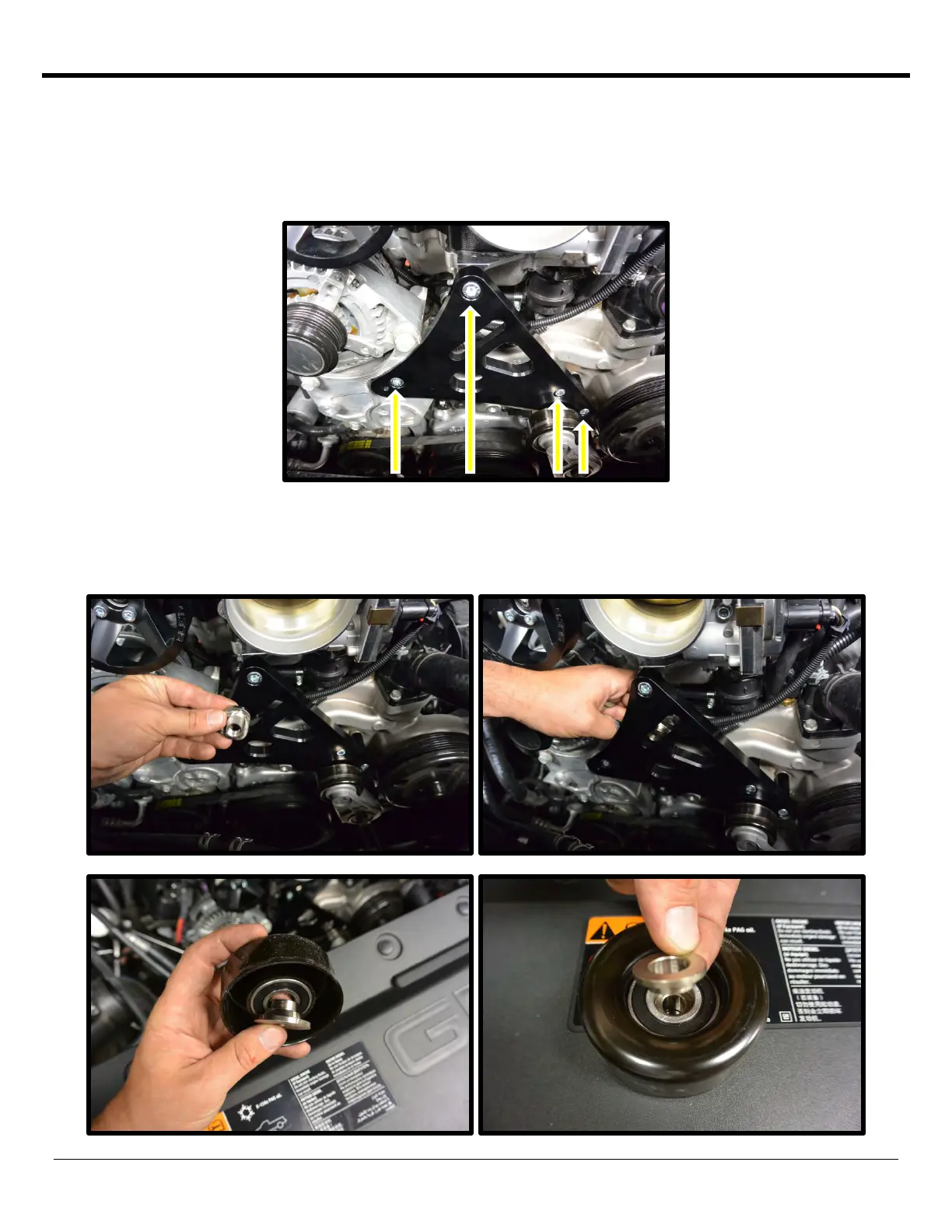
51. Install the front idler plate to the engine by using the supplied 4 spacers and the idler plate. Install the 21.15mm
spacer on the passenger side with the 10mm x 150mm SHCS bolt. Install the (2) 44.32mm spacers on the driver
side with the (2) 8mm x 130mm SHCS. Install plate to the engine. Once you get the (3) bolts started, install the
supplied 8.8mm spacer to the top bolt that connects the idler plate to the intake manifold assembly, secure with
the supplied 10mm x 35mm SHCS. Torque the 8mm SHCS to 15 ft/lbs and the 10mm SHCS to 28 ft/lbs.
Loctite™ (#242 blue) threads.
52. Install the sliding tee-nut to the slotted hole on the front plate (from the back side). Face the shortest end towards
the bottom to allow maximum idler adjustment. Utilize the supplied step spacer with the ½” ID hole to the
backside of the smooth idler pulley. Use the supplied ½” ID step washer on the front of the idler. Use the supplied
½” x 1 ¾” SHCS to secure idler to sliding tee-nut and idler plate. Leave slightly loose for now.
 Loading...