Installation Manual: GM LT1_A1R13E
Last Updated: February 12th, 2019
Page 29 of 36
www.whipplesuperchargers.com
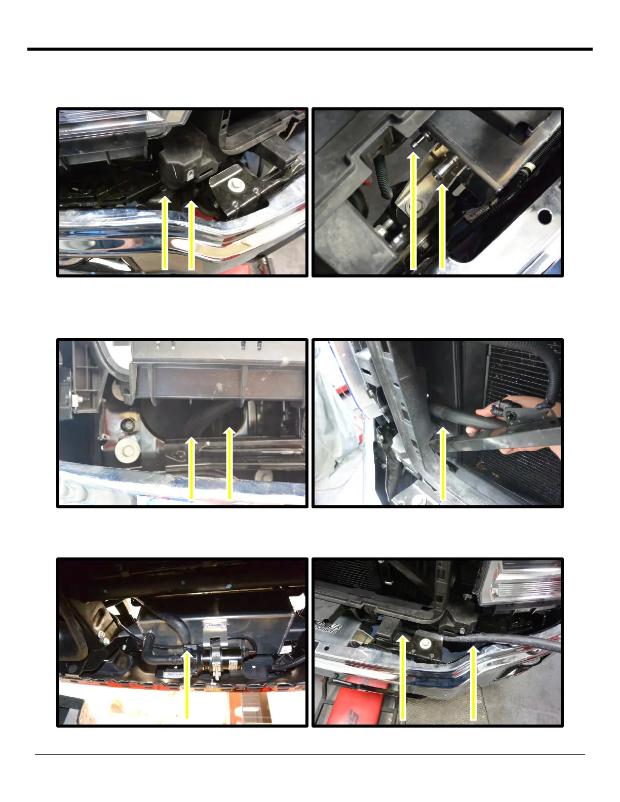
90. Route the hose from the IC filler neck outlet (3/4” ID x 58”) and filler neck vent line (3/8” x 58”) below the airbox,
down on the inside of the forward/passenger side body mount, to the IC water reservoir. Connect both with the
supplied pinch clamps.
91. Route the driver side intercooler inlet hose towards passenger side, below the coolant reservoir outlet and below
the airbox, through the open passage just below the head light. Route behind the plastic radiator support and to
the heat exchanger upper barbed fitting. Connect to heat exchanger using supplied pinch clamp.
92. Install the intercooler pump outlet hose with the 90deg at the pump outlet (3/4” ID #28480). Secure with the
supplied pinch clamp. Route this hose towards driver’s side up over the driver’s side frame rail.
 Loading...