EasyManua.ls Logo

Whirlpool AKP 619/IX/01 User Manual

Whirlpool AKP 619/IX/01
6 pages
To Next Page IconTo Next Page
Page #1 background imageLoading...
Page #1 background image
SERVICE
Whirlpool Europe
Customer Services
AKP 619/IX/01
This documentation is only intended for qualified technicians who are aware of the respec-
tive safety regulations.
Date: 24.09.1997 Subject to modification
Document-No.: 4812 715 16999
Model AKP 619/IX/01
Version 8577 619 42040 Page
Technical data 2
Spare part list 3
Exploded view 4
Wiring diagram 5 - 6
Service Manual
Built-in oven
AKP 619/IX/01
Question and Answer IconNeed help?

Do you have a question about the Whirlpool AKP 619/IX/01 and is the answer not in the manual?

Whirlpool AKP 619/IX/01 Specifications

General IconGeneral
BrandWhirlpool
ModelAKP 619/IX/01
CategoryOven
LanguageEnglish

Summary

Technical Data

Electrical Connection Details

Details the rated voltage, frequency, and main connection types for the appliance.

Power Ratings and Usage

Lists power consumption for heating elements and contemporaneously usable power.

Electrical Components

Identifies specific electrical components like the minute minder and hob control.

Included Accessories

Lists accessories such as baking trays and grid chrome with their dimensions.

Installation Dimensions Diagram

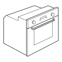
Provides a diagram with key measurements for the oven's installation.

Spare Part List

Oven Door and Frame Parts

Spare parts related to the oven door, including hinges, handle, and frame.

Interior Oven Components

Components like gaskets, shelves, and trays found inside the oven cavity.

Control and Panel Parts

Parts for the control panel, buttons, knobs, and indicator discs.

Heating and Fan Elements

Replacement heating elements, fan wheel, and circulation elements.

Miscellaneous Spare Parts

Includes thermostats, fuses, lamps, nuts, springs, and mounting kits.

Exploded View

Oven Component Breakdown Diagram

A visual diagram illustrating the assembly of the oven with numbered parts.

Part Identification Reference

Maps numbers in the diagram to specific spare parts for easy identification.

Wiring Diagram

Main Electrical Schematic

Shows the overall electrical circuit layout and connections within the oven.

Power Input and Terminals

Details the mains power input, voltage, and terminal block connections.

Wiring Diagram Details

Circuit Point Functions and Colors

Table mapping circuit points to specific functions and wire colors.

Component Labels and Wiring

Explains the labels used for components and their wiring assignments.

Related product manuals