EasyManua.ls Logo

Whirlpool FG1H5040T3NOV - User Manual

Whirlpool FG1H5040T3NOV
28 pages
Print Icon
To Next Page IconTo Next Page
Loading...
HEATERS
TM
WARNING: If the information in these
instructions is not followed exactly, a fire
or explosion may result causing property
damage, personal injury or death.
Do not store or use gasoline or other
flammable vapors and liquids in the
vicinity of this or any other appliance.
WHAT TO DO IF YOU SMELL GAS
Do not try to light any appliance.
+ Do not touch any electrical switch;
do not use any phone in your
building.
+ Immediately call your gas supplier
from a neighbor's phone. Follow the
gas supplier's instructions.
+ If you cannot reach your gas
supplier, call the fire department.
Installation and service must be performed
by a qualified installer, service agency or
the gas supplier.
Gas Water Heater
with the Flame Lock TM
Safety System
Installation
Instructions and
Use & Care Guide
To obtain technical, warranty, or service assistance during or
after the installation of this water heater, call toll free:
1-877-817-6750
When calling for assistance, please have the following
information ready:
I. Model number
2. 7 Digit product number
3. Serial number
4. Date of installation
Table of Contents ...................................................... 2
6510233
September 2001
Question and Answer IconNeed help?

Do you have a question about the Whirlpool FG1H5040T3NOV and is the answer not in the manual?

Summary

Location Requirements and Safety

Flammable Vapors Hazard

Warning against storing or using flammable liquids near the water heater due to explosion risk.

Mobile Home Installation Warning

Prohibits installation in mobile homes to prevent carbon monoxide poisoning.

Site Selection Criteria

Guidelines for choosing a suitable indoor location, considering piping, venting, and clearances.

Gas Supply Information

Gas Supply Hazards and Requirements

Warnings about gas supply hazards and requirements for correct gas type.

LP Gas Specifics

Specific safety warnings and pressure considerations for L.P. gas models.

Combustion Air Supply and Ventilation

Carbon Monoxide Warning

Warning about carbon monoxide poisoning risks associated with improper venting.

Closed System Thermal Expansion

Temperature and Pressure Relief Valve

Valve and Discharge Line Requirements

Specifies requirements for the T&P relief valve and its discharge line for safe operation.

Installation Checklist

Operating Your Water Heater

Pilot Lighting Procedure

Detailed steps for safely lighting the pilot light on the water heater.

Draft and Burner Flame Checks

Emergency Shut Down Procedure

Critical steps for safely shutting down the water heater in an emergency situation.

Water Temperature Regulation

Operational Conditions and Safety

Safety Shut-off System

Details the safety features and conditions that trigger automatic shut-off of the water heater.

Water Heater Maintenance

Temperature and Pressure Relief Valve Test

Guidance on manually testing the T&P relief valve to ensure it functions correctly.

Replacement Parts and Procedures

Burner and Thermocouple Service

Thermocouple Replacement Procedure

Detailed steps for replacing the thermocouple, emphasizing correct parts and handling.

Combustion Chamber and Manifold Service

Igniter System and Gas Control Valve Service

Gas Control Valve;Thermostat Replacement

Detailed steps for removing and replacing the gas control valve/thermostat, including important precautions.

Troubleshooting Guide - Part 1

Burner Ignition and Pilot Light Issues

Provides solutions for issues where the burner will not ignite or the pilot light fails to stay lit.

Troubleshooting Guide - Part 2

Hot Water Recovery and Relief Valve Issues

Addresses slow hot water recovery and dripping relief valves with corresponding solutions.

Combustion and Flame Issues

Troubleshoots combustion odors, smoking, soot, and various burner flame problems.

Overview

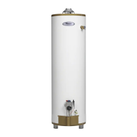
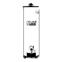
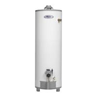
This document is an installation, use, and care guide for a Whirlpool Gas Water Heater with the Flame Lock™ Safety System.

Function Description:

The Whirlpool Gas Water Heater with the Flame Lock™ Safety System is designed to provide hot water for domestic use. It utilizes a gas-fired burner to heat water stored in a tank. The Flame Lock™ Safety System is a key feature, designed to reduce the risk of flammable vapor-related fires by trapping and burning vapors within the combustion chamber. In the event of a flammable vapor incident, the system shuts off the gas supply to the burner and pilot, preventing re-ignition. This safety system permanently disables the water heater if activated. The water heater uses a non-direct, single-pipe vent system to remove exhaust gases to the outside atmosphere. Air for combustion is drawn from the immediate water heater location or ducted in from outside.

Important Technical Specifications:

  • Gas Type: The water heater is designed for a specific type of gas (Natural Gas or LP Gas), which is indicated on the data plate. It is crucial not to use the water heater with any gas type other than the one specified.
  • Gas Supply Pressure: The maximum supply pressure must not exceed the value stated on the data plate. Minimum supply pressure is for input adjustment.
  • Vent Pipe System: Requires UL listed Type B, Double Wall Vent Pipe or Single Wall Vent Pipe. Minimum clearance from combustible materials for Type B is manufacturer-specified, while for Single Wall Vent Pipe, it's 6 inches. Single wall vent pipe cannot be used in attics, crawl spaces, or inaccessible locations, nor can it pass through interior walls.
  • Water Temperature: The thermostat is factory-set to its lowest temperature. Water temperature can be regulated by moving the temperature dial. A preferred starting point is 120°F. Temperatures over 125°F can cause severe burns.
  • Temperature and Pressure Relief Valve: This valve is essential for protection against excessive temperatures and pressures. It must be design-certified by a nationally recognized testing laboratory and its relief pressure must not exceed the working pressure stated on the data plate.
  • Expansion Tank: For closed water systems, a diaphragm-type expansion tank suitable for potable water is recommended, with a minimum capacity of 1.5 U.S. gallons for every 50 gallons of stored water.
  • Water Piping: Should be new piping suitable for potable water (copper, CPVC, or polybutylene). Iron piping and PVC water piping are not recommended.
  • Combustion Air Supply: Requires at least 50 cubic feet of air for every 1,000 BTUH of total input for all gas appliances in an unconfined space. For confined spaces, two permanent openings are required, one within 12 inches of the top and one within 12 inches of the bottom of the enclosure. The minimum free area for openings varies depending on whether air is from inside or outdoors (e.g., 1 square inch per 1,000 BTUH for all air from inside, or 1 square inch per 4,000 BTUH for direct outdoor air).
  • Igniter System: Piezoelectric igniter system with an electric spark for pilot ignition. The spark gap is factory-set at 0.125 inches.
  • Anode Rod: Each water heater contains at least one anode rod, which slowly depletes to protect the glass-lined tank from corrosion. A special anode can be ordered if water odor or discoloration occurs.

Usage Features:

  • Location Requirements: Must be installed indoors, in a vertical position on a level surface, and near the center of the water piping system. It should be located as close as practical to the chimney or gas vent and existing gas piping. Not suitable for mobile homes or areas where flammable liquids are stored.
  • Clearances: Minimum clearances from combustible materials are stated on the data plate. A minimum of 24 inches of front clearance is required for inspection and service.
  • Water Damage Protection: A suitable metal drain pan, at least 2 inches wider than the heater and piped to an adequate drain, should be installed under the water heater to protect against water damage from condensation or leaks.
  • Lighting Instructions: Detailed steps are provided for lighting the pilot, including depressing a reset button and an igniter button, and observing the pilot through a viewport.
  • Temperature Regulation: The temperature dial allows users to adjust the water temperature. A warning is provided about the risk of scalding at higher temperatures.
  • Operational Conditions: Explains normal operational sounds (expansion/contraction, sizzling from condensation), initial smoke/odor from new units, and safety shut-off mechanisms (thermocouple with thermal fuse, high temperature limit switch/ECO).
  • Closed System/Thermal Expansion: Addresses periodic discharge of the temperature and pressure relief valve in closed water systems and recommends installing a diaphragm-type expansion tank or a 125 PSI pressure relief valve in the cold water supply line.
  • Special Applications: Provides guidelines for using the water heater in combination space heating/potable water systems and solar installations, emphasizing the need for tempering valves to limit supply temperature to 120°F in these scenarios.

Maintenance Features:

  • Draining and Flushing: Recommended every 6 months to remove sediment. Instructions include turning off gas and cold water, opening a nearby hot water faucet, connecting a hose to the drain valve, and flushing the tank.
  • 3 Month Inspection: Visual inspection of the venting and air supply system, piping, main burner, and pilot burner for obstructions, damage, soot, leaks, and presence of flammable/corrosive materials.
  • Temperature and Pressure Relief Valve Operation: Manual operation of the relief valve is recommended at least once a year to ensure it's working properly.
  • Self-Cleaning (Some Models): Some models include a self-cleaning device that inhibits lime and sediment buildup.
  • Cleaning the Combustion Chamber and Flame-trap: Involves removing the manifold assembly, vacuuming debris, and reassembling.
  • Anode Rod Inspection/Replacement: The anode rod should be removed and inspected every 3 years. If more than 50% depleted, it should be replaced to prolong tank life and address "rotten egg smell" from hydrogen sulfide gas.
  • Burner and Pilot Flame Inspection: Instructions for inspecting burner flames through the viewport to ensure a soft blue flame.
  • Troubleshooting Chart: A comprehensive chart is provided to diagnose and correct common issues such as burner not igniting, smelly water, yellow/lazy flame, pilot not lighting, high operation costs, and insufficient hot water.
  • Replacement Parts: Instructions for ordering replacement parts, including model, serial, product number, type of gas, item number, and part description. Emphasizes using factory-authorized Flame Lock™ safety system components.
  • Gas Control Valve/Thermostat Replacement: Detailed steps for removing and replacing the gas control valve/thermostat, highlighting the use of factory-authorized replacement parts and proper sealing.

Whirlpool FG1H5040T3NOV Specifications

General IconGeneral
BrandWhirlpool
ModelFG1H5040T3NOV
CategoryWater Heater
LanguageEnglish

Related product manuals