

T
Terry LeblancAug 2, 2025
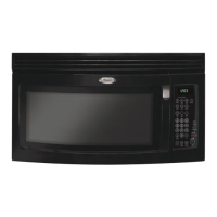
What to do if the colon is flashing on my Whirlpool MH3184XPB?
- JJohn JonesAug 2, 2025
If you see a flashing colon on your Whirlpool Microwave Oven, simply press any key to stop the flashing. When in standby mode, the colon should then be steady.