3-7
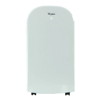
5. To remove the capacitor:
a) Remove the two screws from the top
and bottom of the control panel assem-
bly.
Screw (black)
Screw
Control Panel
b) Pull the housing out the unit and posi-
tion it as shown below.
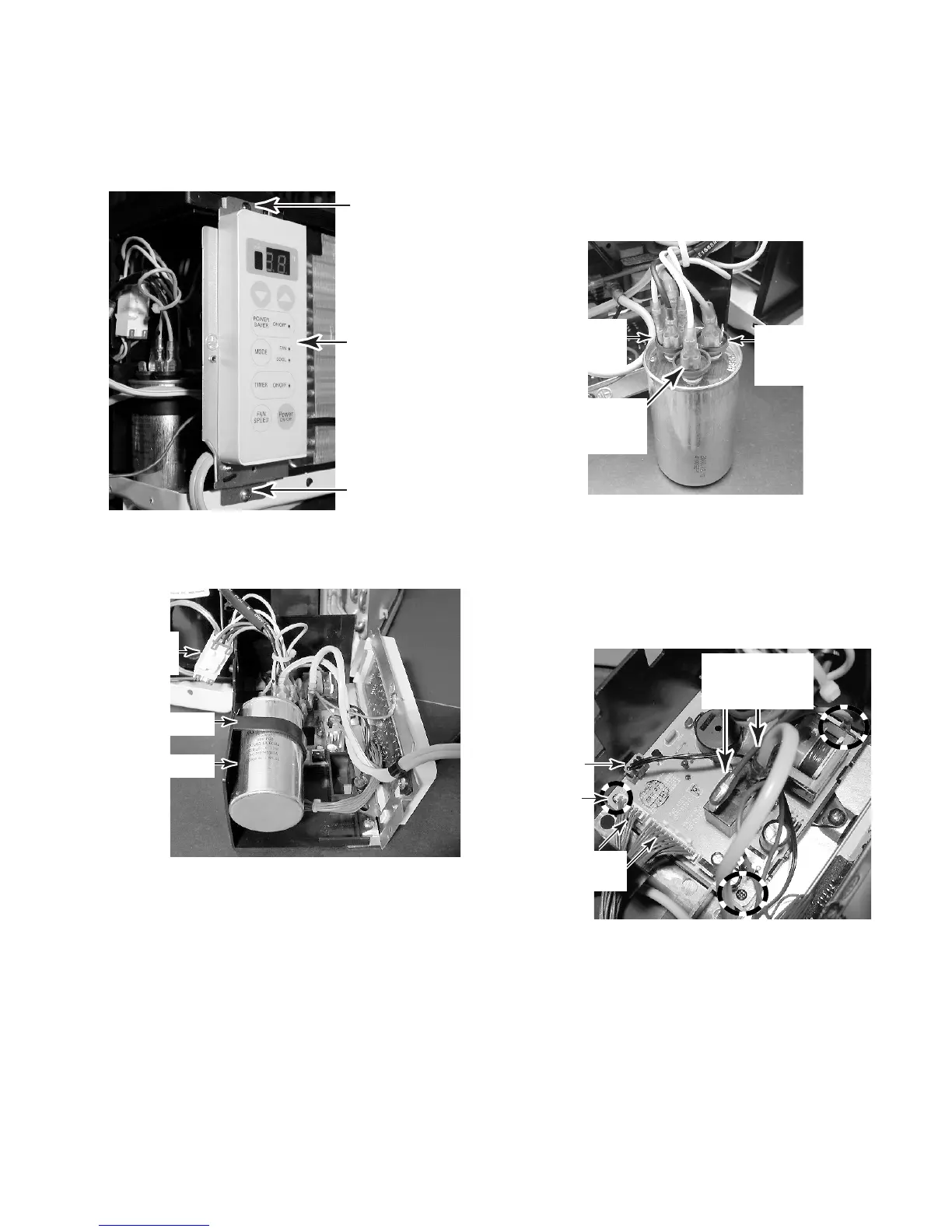
6. To remove the main PCB:
a) If not already done, remove the capaci-
tor (see step 5). NOTE: It is not neces-
sary to perform step 5e.
b) Remove the three screws from the main
PCB.
c) Disconnect the following connectors
from the main PCB:
• Fan motor connector (see the photo
to the left for the location).
• 6- & 11-wire connectors (brown wires).
• 4-wire connector (from thermistor).
• Smooth power cord lead from lug 3
and blue wire from lug 4 of the relay.
d) Unclip the PCB from the holder.
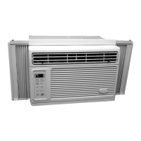
c) Discharge the capacitor by touching
one lead of a 20,000 Ω resistor to the
common (C) terminal, and the other
lead to each of the other two termi-
nals (marked FAN & HERM next to
the terminals).
d) Slide the capacitor out of the mounting
strap.
Capacitor
Strap
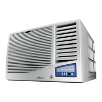
e) Disconnect the wires from the following
capacitor terminals:
• Yellow wire to 2-lug terminal (FAN).
• Red wire to 3-lug terminal (HERM).
• Black, (2) orange, and ribbed power
cord lead to 4-lug terminal (C).
4-Lug
Terminal
(C)
2-Lug
Terminal
(FAN)
3-Lug
Terminal
(HERM)
Fan Motor
Connector
4-Wire
Connector
Blue Wire &
Smooth Power
Cord Lead
6- & 11-Wire
Connectors
Screw
(1 of 3)