Sealed System Repair
R600A Sealed System
n
2-3
Sealed System Access Procedure
¾ First, Verify Failure
¾ REQUIRED to Acvate the Combusble Gas Detector before
any work is started. Place the Detector at the lowest point
of the work area.
¾ Ensure Pre-Work Checks in Secon 2.2 are Completed.
¾ If you are working on a Sealed system with a Three Way
Valve.
¾ Position 3-Way Valve to Home Position.
¾ Enter diagnostic mode.
¾ Initiate Step To open the Three Way Valve (refer to tech
sheet) and wait 1 minute.
¾ Unplug the refrigerator.
¾ Remove the Machine Compartment Cover.
¾ Attach quick disconnect fittings to High Side Fitting.
¾ Attach to Schrader Valve if present.
¾ If Schrader Valve is not present, use piercing pliers to access
High Side of the sealed system. Attach quick disconnect
fitting to the piercing pliers. If the compressor is non
functional, connect a second piercing pliers to the
suction process tube.
R600a Refrigerant
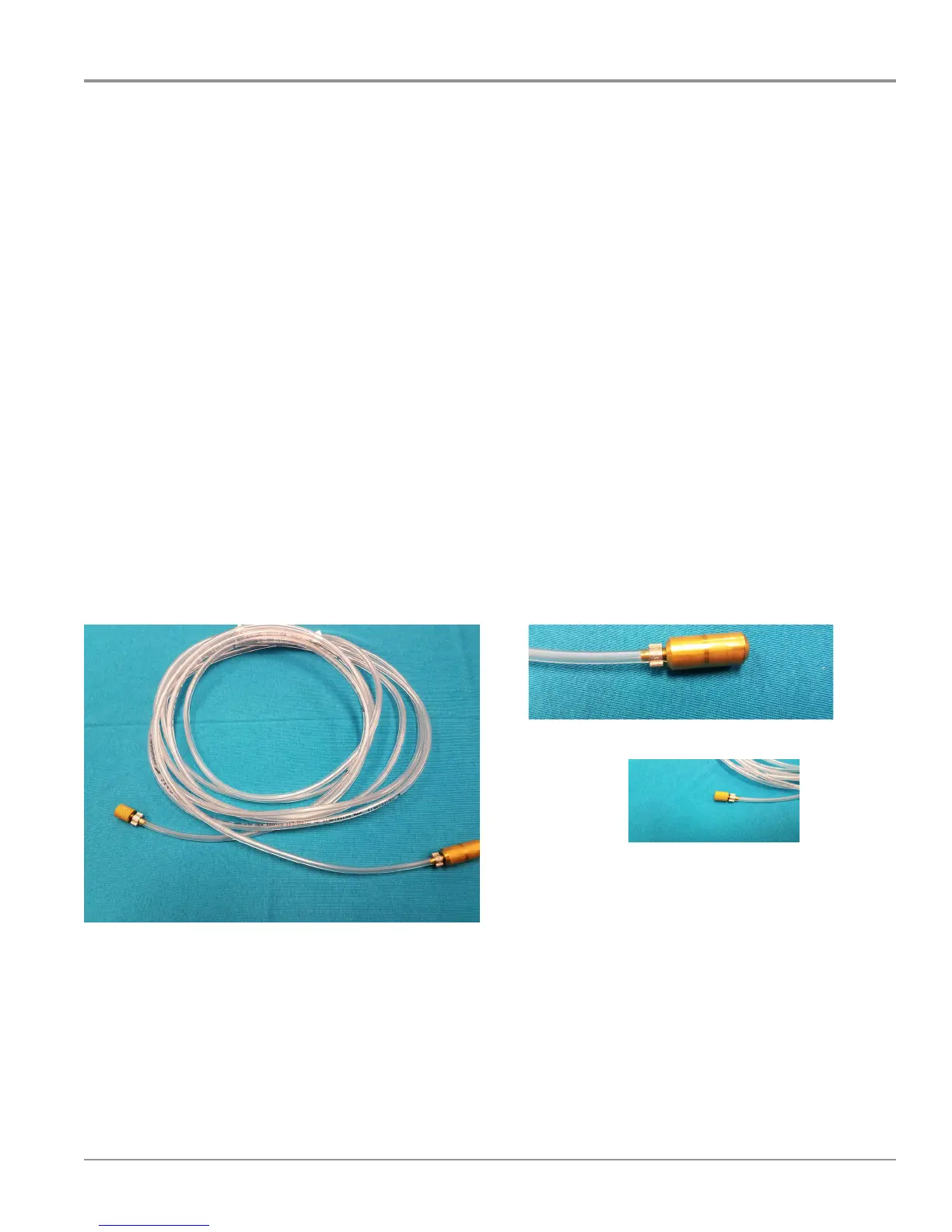
• The LOKBOX Charging Facility is equipped with a 20’ PVC
Recovery Hose. This length should be sucient to reach an
outdoor locaon in most instances.
• Unlike tradional CFC’s and HCFC’s, the EPA allows venng
of R600a refrigerant to the outside atmosphere.
• Venng is the preferred method of removing refrigerant
from a sealed system.
Venting Process
¾ When (all requirements are met, venng allows the refrigerant
to be safely dispersed in the natural environment, removing
the hazard of concentrang and transporng ammable
immediately.
¾ When venng, it expands to atmospheric pressure. Venng
mes will vary for many reasons, including but not limited
to, the size of charge, atmospheric pressure, whether the
compressor is running. Connue venng the appliance for an
addional 10 minutes aer the pressure coming out ends.
¾ ATTENTION: Do not vent R600a refrigerant indoors.
¾ ATTENTION: Ensure there is no source of ignion near the
discharge hose.
R600a vent locations must meet the following criteria:
• R600a must be discharged to the outside environment.
• Discharge locaon must not be a public area or area where
people are unaware of the procedure taking place.
• There must be no sources of ignion near the hose discharge.
• Ensure that there is no posibilty for refrigerant to be blown back
into any buildings, or to a locaon below ground level.
Sealed System Refrigerant Venting Procedure
(Preferred)
¾ Route the weighted end of the 20’ PVC Recovery Hose to an
outdoor locaon.
¾ Connect the opposite end on the 20’ Recovery Hose to the
quick disconnect ng on the High Side piercing pliers to begin
venng.
¾ If the compressor is funconal, run the compressor to speed the
venng process.
¾ Monitor the Recovery Hose and discharge point.
¾ Ensure the hose remains kink free.
¾ Ensure the Refrigerant Venng Requirements are met
connually throughout the venng process.
¾ Observe the mirage eect at the hose discharge as the R600a
refrigerant exits. Note when the mirage eect stops.
¾ A mirage is a naturally occurring opcal phenomenon in which
light rays are bent to produce a displaced image of distant
objects or the sky.
¾ Hitting the compressor with a Rubber Mallet at this time will
remove any trapped R600a from the oil.
¾ Continue Venting for an additional 10 minutes to ensure
system is fully vented. After the sealed system is fully vented,
disconnect the Recovery Hose from the quick disconnect ng.