Sealed System Repair
R600A Sealed System
n
2-5
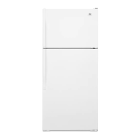
¾ Connect the refrigerant hose (zip ed to the charging
case) to the extracon valve (the other end should be
ghtly connected to the one-way valve aached to
charging case).
Sealed System Evacuation
Due to the narrow charging tolerances associated with
R600a refrigerant, it is necessary to draw a deep vacuum of
at least 28” of vacuum to ensure proper evacuaon. Oil in
the vacuum pump should be changed frequently to ensure
the ability to draw a deep vacuum.
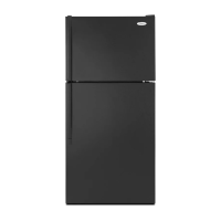
¾ For evacuaon connect both sides Low and high -
Connect a hose to gauge manifolds side port and the
opposite end to the upper brass-T.
¾ Connect an addional charge hose to a Gauge manifold
lower male port and the other hose end to the 2nd
quick disconnect adapter. Unclip and thread the quick
disconnect adapter cap onto the high side charge port,
DO NOT CONNECT QUICK DISCONNECT TO THE ADAPTER
CAP THAT IS ON THE PRODUCT AT THIS TIME.
¾ Connect a charge hose with shut o valve between vacuum
pump and lower Brass T side port.
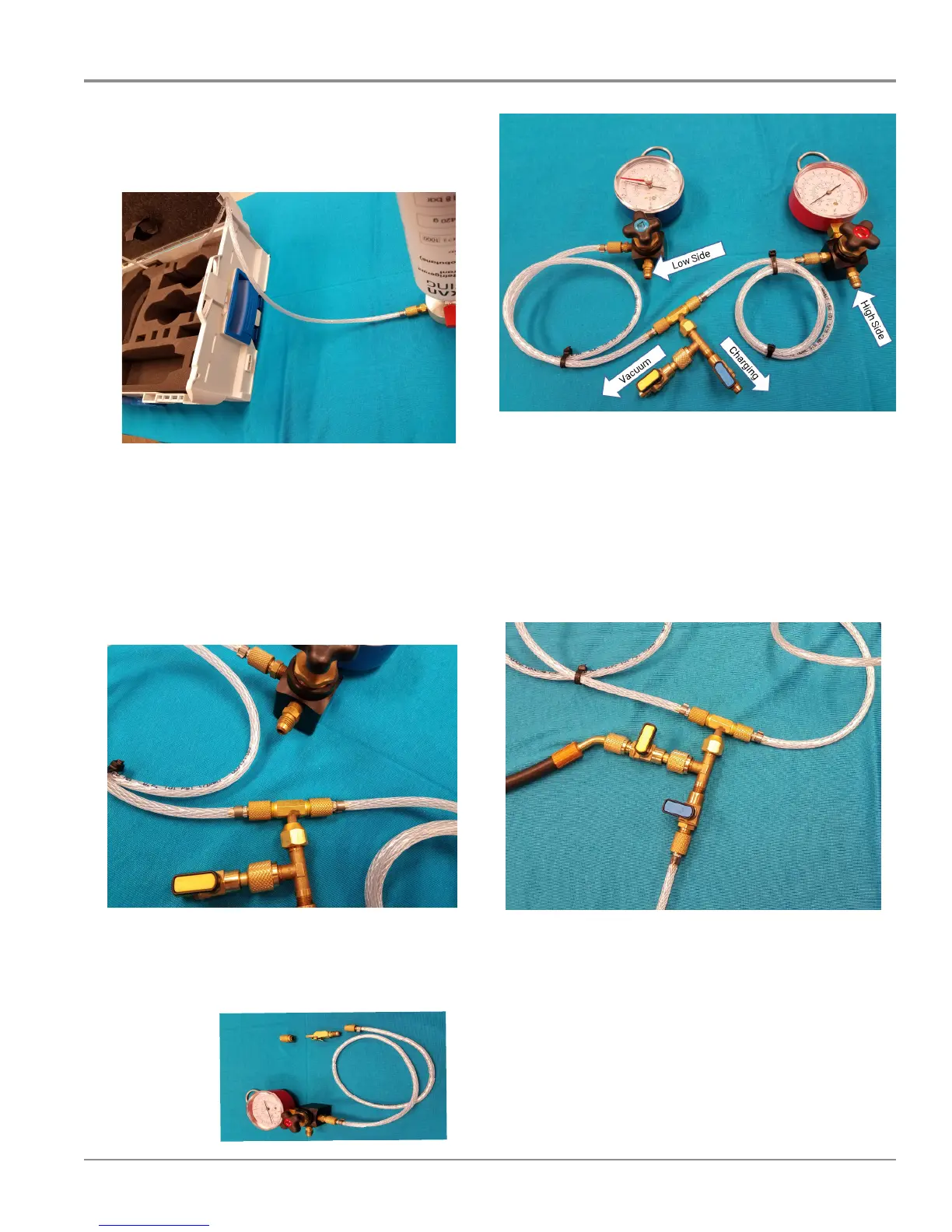
Gauges and Hose Connection Diagram
¾ Once you have all of your connecons secure you can
start the Vacuuming and Charging Process