2-6
n
R600A Sealed System
Sealed System Repair
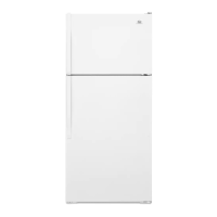
¾ Turn the vacuum pump on and let it warm up for a few
minutes (warm to touch). Once warm open the ball
valve at the hose coming from the vacuum pump to
T-connecon. Open the Low Pressure gauge manifold
valve. Watch needle on the low pressure gauge unl it
reaches it’s lowest vacuum reading posion.
¾ When the Low Pressure gauge needle reaches the lowest
vacuum reading, set the adjustable set pointer to cover
the vacuum needle. Close the ball valve on vacuum
pump hose. The Low Pressure / Vacuum gauge must hold
without dropping for a minimum of 60 seconds. This test
ensures that all connecons of the lling equipment are
ght and leak free.
¾ Connect the quick coupling to the Low and High side
compressor lling tube. (If evacuang both sides) connect
the High Pressure quick coupling to the dryer. Slowly open
the ball valve in line to the vacuum pump.
¾ Evacuate unl the Low Pressure gauge reaches the
previously set posion (about 5 mintes) of the adjustable
shadow needle. Close o the Valve to the Vacuum Pump
and wait at lease 60 seconds.
¾ Watch the shadow needle for any deecon. If you do
not see any movement you can connue and Evacuate
for adddional 10 minutes.
¾ If you do see movement in the needle you may have a
leak in the sealed system that needs to be repaired.
¾ If no pressure change (vacuum needle stays steady
behind shadow needle), the charging process can be
started.
Charging Process
¾ At this point you can remove the High side quick connect
from the lter dryer. Keep the High side valve open and
connected. This is to remove the remaining refrigerant in
the hoses in the last step.
¾ Close the ball valve to the charging staon at the lower
T-ng. Switch on the scale and set to zero.
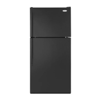
¾ Open the discharge valve on the refrigerant bole and
allow the gas to ow into the hoses.
Discharge valve on the refrigerant bottle
¾ Note for liquid filling (This is the preferred process)
¾ When filling with liquid refrigerant, the bottle is screwed
into the holder with the closed extraction valve in place
on the bole. The bole is placed upside down on the
scale.
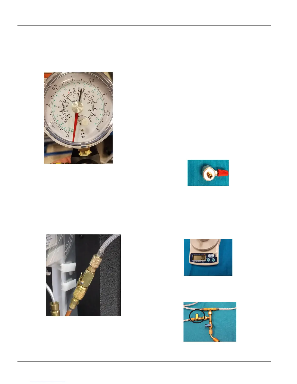
¾ Switch the scale on and reset to zero(Figure S). Make
sure Lower T-connecon ball valve to charging case is
closed.
Figure S
¾ Open the valve that is connected to the R600a and ll
the hoses with refrigerant up to the ball valve of the
charging case T-piece(Figure T).
Figure T
T-connection ball valve to charging case