PAGE 6
FOR SERVICE TECHNICIAN’S USE ONLY
DO NOT REMOVE OR DESTROY
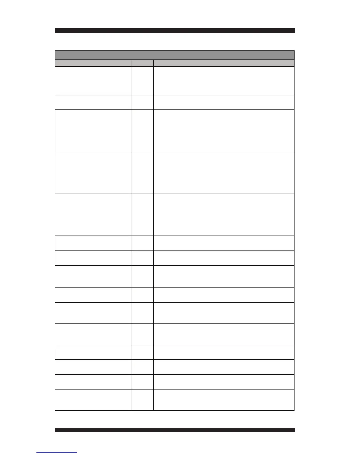
Component Activation Chart
Output On/Off Details
UI Component Test N/AUpon activation, all LEDs are turned on. Pressing each button turns off
its LED. Rotating the cycle selector knob turns off each LED. Pressing
the ATM buttons changes their on-screen representations from black
to green.
Motor YES Status (On/Off) NOTE: Door must be closed.
If the motor does not turn on, go to TEST #3, page 12.
Heater1 (Electric)/ Heat On (Gas) YES Status (On/Off) NOTE: Door must be closed.
Attributes: Exhaust & Inlet Thermistor Reading.
When you turn on heat, the motor is turned on as well. If temp is
too high, system will automatically turn off heat.
• If the motor does not turn on, go to TEST #3, page 12.
• If no heat is detected, go to TEST #4, page 13.
Heater2 (Electric Only) YES Status (On/Off) NOTE: Door must be closed.
Attributes: Exhaust & Inlet Thermistor Reading.
When you turn on heat, the motor is turned on as well. If temp is
too high, system will automatically turn off heat.
• If the motor does not turn on, go to TEST #3, page 12.
• If no heat is detected, go to TEST #4, page 13.
Heater 1 & 2 (Electric Only) YES Status (On/Off) NOTE: Door must be closed.
Attributes: Exhaust & Inlet Thermistor Reading.
When you turn on heat, the motor is turned on as well. If temp is
too high, system will automatically turn off heat.
• If the motor does not turn on, go to TEST #3, page 12.
• If no heat is detected, go to TEST #4, page 13.
Inlet ThermistorN/A Status (F°, C°, and Resistance)
If inlet thermistor reading is out of range, go to TEST #4a, page 16.
Exhaust ThermistorN/A Status (F°, C°, and Resistance)
If exhaust thermistor reading is out of range, go to TEST #4a, page 16.
Moisture Sensor N/AStatus (Open/Closed)
• Place finger over both sensor strips. If sensor status does not change,
go to TEST #5, page 18.
Door Status N/AStatus (Open/Closed)
• If opening the door does not change status, go to TEST #7, page 20.
CCU Line Voltage 1N/A Status (L1 Voltage Measurement) NOTE: Door must be closed.
When measuring L1, the motor and heater are activated.
• If L1 is absent, go to TEST #1, page 9.
CCU Line Voltage 2 (Electric Only)N/A Status (L2 Voltage Measurement) NOTE: Door must be closed.
When measuring L2, the motor and heater are activated.
• If L2 is absent, go to TEST #1, page 9.
Air Flow N/AStatus (Normal/Restricted) NOTE: Door must be closed.
• If air flow does not turn on, go to TEST #4, page 13.
Drum Light YES Status (On/Off)
• If drum light does not turn on, go to TEST #1, page 9.
Buzzer YES Status (On/Off)
• If buzzer does not sound, go to TEST #6, page 19.
Myst Valve YES Status (On/Off) After being turned on, the myst valve automatically
deactivates after 30 seconds if not turned off.
• If myst valve does not turn on, go to TEST #9, page 21.
COMPONENT ACTIVATION CHART





 To Next Page