MSEX0025_rev01
4
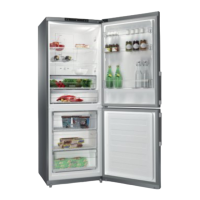
When the door is closed, the magnet is on the Interface Board, which informs the Potency Module causing
the corresponding Lamp to remain OFF. When the door is opened, the magnet stays away from the
Interface Board and the Lamp turns ON. The technician can test the activation system by using a round
magnet with approximately 20 mm in diameter and 5 mm in height (preferably).
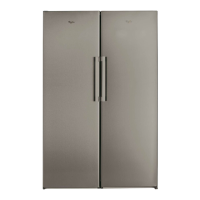
The WRM34, WBM35 models are fitted with only one lamp on the Refrigerator Compartment, but their
activation system is the same of the others models
.
3.2 – Product Electronic Control System :
The Refrigerator is fully operated by an Electronic Control System which performs several functions. This
electronic control system consists of the following components:
• Potency Module
• Temperature Sensor
• Interface Board
The following described are the characteristics of each control system component:
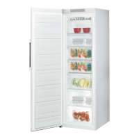
• Potency Module :
Fixed in the Cabinet, located beside the Compressor and behind to the metallic cover. The connection from
the Potency Module to the Electric Line and Power Cable is made via connectors with fault-intolerant
fittings.
The replacement of the connectors connecting to the Module is possible through an adapting process,
avoiding the need for changing the Cabinet or Refrigerator. See how to proceed by referring to Item 6.8 -
Adapter for connecting to Potency Module.
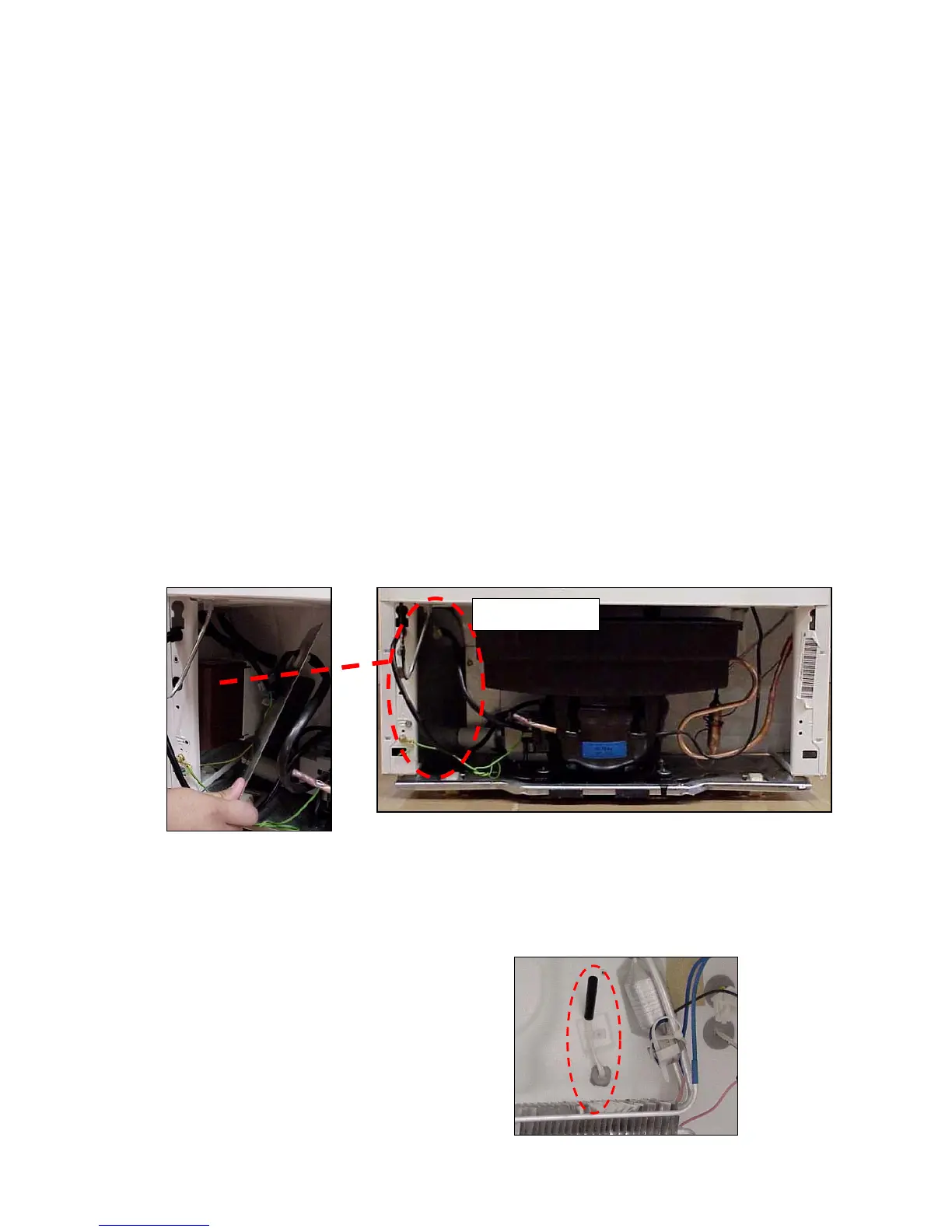
• Temperature Sensor :
Responsible for monitoring the air temperature on the
Evaporator input, sending signals to the Potency
Module. It is connected to the Potency Module for
Cabinet internal wiring.
Potency Module