EasyManua.ls Logo

Whirlpool WFG525S0JW - User Manual

Whirlpool WFG525S0JW
3 pages
Print Icon
To Next Page IconTo Next Page
Loading...
Membrane
Keypad
P5-1
P5-3
Broil (P5)
K2
BU
BK
BK/WH
BK
RD/WH
P4-4
P4-3
Bake (P4)
K3
P11
Keypad
Oven Control LCX 1.0
P7
Not Used
P9
Not Used
P2-6
P2-3
K5
P2-1
P2-2
K4
K6
BK
BR
BK/WH
P1-1
BK
BU
WH
P1-3
Power In (P1)Power Supply
Switch Common
P3-3
P3-2
P3-1
RTD Oven
P3-5
RTD Common
P3-4
Main Oven Temp
Sensor (RTD)
Door
Position Switch
BU
GY
YL
VT
VT
Oven Light 40W
Oven Lock Motor
M
WH
RD
OR
BK
RD to OR
216
Solenoid
Valve
J1-6
J1-7
J1-4
J1-1
J1-2
J1-3
J1-10
DSI Board
BK WH
L1 N
Convection Fan (on some models)
M
BU
BU/WH
Oven Lock Motor Switch
P2 (Blue)
BK BR BU
1
BK/
WH
P1 (Red)
BK
1
WH
1
3
4
BK
BU
P4 (Red) P5 (Blue)
1
3
4
BK
BK/WH
P3 (Red)
VT
VT
GY
BU
YL
1
Thermo Fuse
LEGEND
Indicator
Light
ThermistorNon-resettable
Fuse
Connection No
Connection
On
Some
Models
In-Line
Connection
Connector P2,
Position 1
Circuitry
Enclosed
Within
Terminals Single
Switch
Thermal Switch
(opens on
heat rise)
Thermal Switch
(closes on
heat rise)
Resistor
or Element
Motor Incandescent
Light
Triac
P2-1
M
©2019 All rights reserved. 04/19
W11351206A
Quick Connect Plugs Oven Control Wiring Diagram Cooktop Wiring Diagram
FOR SERVICE TECHNICIAN’S USE ONLY
Wiring Diagram
Do Not Remove Or Destroy
W11351206A
NOTE: This sheet contains important Technical Service Data.
FOR SERVICE TECHNICIAN ONLY
DO NOT REMOVE OR DESTROY
P1 through P10 for oven controls
P21 through P25 for cooktop
NOTE: Schematic shows oven door open and elements off.
Caution: Label all wires prior to disconnection when servicing controls. Wiring errors can cause improper and dangerous operation. Verify proper operation after servicing.
BK TN
L1
N
BK TN
BK TN
BK TN
BK TN
BK
Spark
Module
GND
Cooktop Ignitors
Ignitor
Question and Answer IconNeed help?

Do you have a question about the Whirlpool WFG525S0JW and is the answer not in the manual?

Summary

Oven Control Wiring Diagram

Quick Connect Plugs - Oven Controls

Details connector pin configurations and wire colors for oven controls (P1-P10).

Membrane Keypad

The user interface panel connected to the oven control board.

Oven Control LCX 1.0

The central electronic control unit managing oven functions.

Power Supply

Provides the main electrical power input for the oven control system.

Cooktop Wiring Diagram

Cooktop Ignitors

Illustrates the wiring for the ignitors used in cooktop burners.

Spark Module

The component responsible for generating ignition sparks for the cooktop.
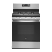
Whirlpool WFG525S0JW Specifications

General IconGeneral
Stylefreestanding
Main Capacity5 cu. ft.
Temperature Probeno
Convectionno
Grillno
Number of Burners5
Number of Racks2
Control Typeknobs; touchpad
Interior Lightyes
Wi-Fino
Fuelgas; natural gas
Voltage120 volts
Current15
Weight and Dimensions IconWeight and Dimensions
Depth27 3/4 inch
Height47 7/8 inch
Width30 inch; 29 7/8 inch

Related product manuals