EasyManua.ls Logo

White Outdoor ZT Zero 17AA5A4G790 User Manual

White Outdoor ZT Zero 17AA5A4G790
26 pages
To Next Page IconTo Next Page
Page #1 background imageLoading...
Page #1 background image
Service Manual
ZT Zero Turn Rider
MTD Products Inc. - Product Training and Education Department
FORM NUMBER - 769-01421
12/2004
NOTE: These materials are for use by trained technicians who are experienced in the service and repair of outdoor power
equipment of the kind described in this publication, and are not intended for use by untrained or inexperienced individuals.
These materials are intended to provide supplemental information to assist the trained technician. Untrained or inexperi-
enced individuals should seek the assistance of an experienced and trained professional. Read, understand, and follow all
instructions and use common sense when working on power equipment. This includes the contents of the product’s Oper-
ators Manual, supplied with the equipment. No liability can be accepted for any inaccuracies or omission in this publication,
although care has been taken to make it as complete and accurate as possible at the time of publication. However, due to
the variety of outdoor power equipment and continuing product changes that occur over time, updates will be made to these
instructions from time to time. Therefore, it may be necessary to obtain the latest materials before servicing or repairing a
product. The company reserves the right to make changes at any time to this publication without prior notice and without
incurring an obligation to make such changes to previously published versions. Instructions, photographs and illustrations
used in this publication are for reference use only and may not depict actual model and component parts.
© Copyright 2005 MTD Products Inc. All Rights Reserved
www.mymowerparts.com
For Discount White Outdoor Parts Call 606-678-9623 or 606-561-4983
Question and Answer IconNeed help?

Do you have a question about the White Outdoor ZT Zero 17AA5A4G790 and is the answer not in the manual?
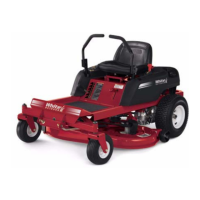
White Outdoor ZT Zero 17AA5A4G790 Specifications

General IconGeneral
Cutting Width42 inches
Fuel Capacity3 gallons
Deck MaterialSteel
Turning RadiusZero-turn
Cutting Height1.5 - 4 inches
Weight500 lb
Warranty3 years residential

Summary

General Information

ZT Model Overview

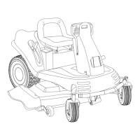
Details ZT17 and ZT22 models, engines, and decks.

Deck Leveling

Adjust Deck Pitch

Set front-to-back deck pitch to 1/8"-1/4" lower in front.

Adjust Deck Side-to-Side Level

Ensure equal side blade tip height from ground.

PTO / Deck Belt Replacement

Remove PTO/Deck Belt

Sicken belt using tensioner arm and remove from pulleys.

Deck Removal

Detach and Slide Deck

Release rear hanger arms and slide deck forward.

Blade Drive Belt Removal

Remove Belt Covers and Belt

Remove belt covers and then the drive belt from pulleys.

Idler Arm Removal

Remove and Inspect Idler

Remove idler securing screw and check for wear.

Blade Spindle Removal

Detach Blade Spindle

Remove deck, covers, belt, and spindle nut to detach spindle.

Drive Belt Replacement

Install New Drive Belt

Tension arm, route and install new belt onto pulleys.

Servicing Electric PTO Clutch

Remove PTO Clutch

Unplug connector, remove clutch bolt, and take clutch off crankshaft.

Adjust PTO Clutch Air Gap

Set air gap to .010"-.015" using a feeler gauge.

Transmission Replacement

Prepare for Transmission Removal

Disconnect brake rod, arm, and brace bolts.

Remove Transmission Unit

Remove mounting bolts and detach transmission from frame.

Steering Linkage: Adjustment

Confirm Hydro Neutral Control

Verify both hydros are correctly adjusted for neutral.

Adjust Neutral Return Assembly

Loosen screw to adjust neutral return assembly for centering.

Steering Linkage: Adjustment

Secure Ferrule and Adjust Stop Bolts

Secure ferrule to control rod and adjust stop bolts for tracking.

Steering Linkage: Adjustment

Test and Adjust Reverse Safety Switches

Test PTO disengagement in reverse; adjust switch bracket if needed.

Pivot Bar

Remove Caster Wheel Assembly

Remove wheel assembly from caster bracket using wrenches.

Inspect Pivot Bar Bearings

Inspect flange bearings on pivot axle for wear.

Pivot Bar

Remove Axle Shaft

Remove hex cap screws to detach axle shaft from frame.

Seat Removal

Detach Battery and Seat Knobs

Disconnect battery lead and remove seat mounting wing knobs.

Remove Seat Assembly

Slide seat spacers to align and lift seat from mounting bracket.

Seat Removal

Disconnect Seat Safety Switch Wires

Disconnect electrical connections from the seat safety switch.

Console Removal

Remove Console Mounting Screws

Unscrew console from frame and seat frame.

Console Removal

Detach Lapbars and Console

Remove lapbars, then carefully lift the console from the unit.

Battery Removal

Prepare for Battery Removal

Disconnect battery leads, remove strap, and fuel pump.

Remove Battery from Unit

Pull battery out, or remove with console if applicable.

Fuel Tank Removal

Prepare Fuel Tank Access

Remove seat, disconnect battery, remove fuel tank mounting wire.

Detach and Remove Fuel Tank

Disconnect electrical connector and slide fuel tank out.

Fuel Tank Removal

Free Brake Rods and Seat Frame

Remove hairpin from brake rod, disconnect rods, remove seat frame screws.

Control Shaft Replacement

Disconnect Controls and Shaft

Disconnect ferrule, remove cap screw securing control hub.

Control Shaft Replacement

Remove Control Hub and Bearings

Remove control hub, lapbar rod, and inspect bearings.

Deck Lift Shaft Replacement

Prepare for Deck Lift Shaft Removal

Complete seat, console, battery, and fuel tank wire removal.

Deck Lift Shaft Replacement

Remove Brake Handle and Cables

Remove brake handle components and deck lift cables.

Detach Brake Rods from Shaft

Remove center hairpin and slide concentric shaft to release brake rods.

Deck Lift Shaft Replacement

Remove Shaft End Clips and Bearings

Remove E-clips and hex flange bearings from the deck lift shaft.

Clear Space and Extract Assembly

Support frame, create clearance to slide deck lift assembly out.

Deck Lift Shaft Replacement

Remove Deck Lift Shaft and Handle

Slip the deck lift shaft and handle out of the rear of the unit.

Electrical System Components

Locate Seat Safety Switch

Identify the seat safety switch under the seat assembly.

Locate Parking Brake Switch

Identify the parking brake switch under the seat box frame.

Electrical System Components

Identify Neutral Switches

Locate neutral switches in consoles; note open/closed states.

Identify Reverse Switches

Locate reverse switches under lapbars; note normally closed state.

Electrical System Components

PTO Switch Operations and Testing

Understand PTO switch functions and test voltage.

Key Switch Identification and Tests

Identify key switch types and perform continuity tests.

Relays Location and Identification

Locate and identify the Seat, PTO, and Brake relays.

Electrical System Components

Relay Functional Tests

Perform tests for ground and power on Seat, PTO, and Brake relays.

Starter Solenoid Location and Grounding

Locate starter solenoid and ensure proper ground connection.

Electrical System Components

Component Wiring Diagram Labels

Reference labels for various electrical components in the diagram.

Electrical System Components

Electrical System Wiring Diagram

Overview of the complete electrical system schematic.

Related product manuals