EasyManua.ls Logo

White Rodgers 1311 User Manual

White Rodgers 1311
8 pages
To Next Page IconTo Next Page
Page #1 background imageLoading...
Page #1 background image
Printed in U.S.A.
Operator: Save these instructions for future use!
FAILURE TO READ AND FOLLOW ALL INSTRUCTIONS CAREFULLY BEFORE
INSTALLING OR OPERATING THIS CONTROL COULD CAUSE PERSONAL
INJURY AND/OR PROPERTY DAMAGE.
DESCRIPTION
These water valves provide a low cost system of zoned tem-
perature control wherever hot water is the heating medium. In
new construction, the heating piping system can be laid out to
produce any number of independent temperature controlled
zones by use of these valves.
In existing buildings, a variety of zone heating combinations can
be obtained, depending on the particular piping lay-outs. Each
zone requires one water valve and one thermostat, but only
one circulator is required for the entire system. New con-
struction properly piped, will not require flow control valves,
since the water valve itself performs this function.
Existing construction, where flow control valves have been
installed, will operate quite satisfactorily without removing the
existing flow control valves.
PRECAUTIONS
This zone valve motor is intended for use with a low voltage
system; do not use this zone valve with a millivolt or line voltage
system. If in doubt about whether your wiring is millivolt, line or
low voltage, have it inspected by a qualified heating contractor
or electrician.
Do not exceed the specification ratings.
All wiring must conform to local and national electrical codes and
ordinances.
To prevent electrical shock and/or equipment damage,
disconnect electric power to system at main fuse or
circuit breaker box until installation is complete.
To prevent injuries from scalding always drain system
before unlatching valve assembly from body.
INSTALLATION INSTRUCTIONS
TYPE 1311
HYDRONIC ZONE VALVES
(3 WIRE)
The schematic shows the valve in the closed position. As the
thermostat calls for heat, the valve motor is energized and
begins to open the valve. Soon thereafter side “A” of motor
switch makes with the holding contacts. This contact provides a
holding circuit to prevent the valve from stopping part way
through its cycle if the thermostat is changed to the satisfied
Do not use on circuits exceeding specified voltages.
Higher voltages will damage control and could cause
shock or fire hazard.
SPECIFICATIONS
All guarantees are void if these specifications are exceeded.
Maximum water temperature: 240°F (115°C)
Maximum system pressure: 50 PSI
Differential across valve: 15 PSI
Electrical Rating:
Valve Motor: 25 VAC (.40 Amp.)
Auxiliary Contacts: Do not exceed 2.0 Amp. at 25 VAC
(Terminals 2 and 3)
Timing: Approximately 45 seconds from full open to full close
or full close to full open.
Friction loss equivalents:
3/4" valve – 2-1/2 ft. copper tubing
1" valves – 4 ft. copper tubing
1-1/4" valves – 7 ft. copper tubing
PRINCIPLE OF OPERATION
position. Just before the valve reaches the full-open position,
side “B” of motor switch closes (providing a low voltage auxiliary
circuit for starting burner and/or circulator). The motor stops with
the valve in the open position when side “A” of motor switch
breaks the holding contact. (Completing a circuit through con-
tact “6” and the thermostat anticipator.)
PART NO. 37-5421B
Replaces 37-5421A
9812
WHITE-RODGERS DIVISION
EMERSON ELECTRIC CO.
9797 REAVIS RD., ST. LOUIS, MO. 63123
(314) 577-1300, Fax (314) 577-1517
9999 HWY. 48, MARKHAM, ONT. L3P 3J3
(905) 475-4653, FAX (905) 475-4625
CAUTION
!
CAUTION
!
WARNING
!
WHITE-RODGERS
Question and Answer IconNeed help?

Do you have a question about the White Rodgers 1311 and is the answer not in the manual?

White Rodgers 1311 Specifications

General IconGeneral
BrandWhite Rodgers
Model1311
CategoryControl Unit
LanguageEnglish

Summary

Type 1311 Hydronic Zone Valves Installation Instructions

Operator Safety Instructions

Save instructions for future use and follow all instructions carefully.

Description of Hydronic Zone Valves

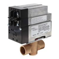
Explains the function and application of hydronic zone valves in heating systems.

Precautions for Installation and Operation

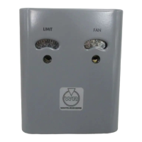
Covers safety cautions regarding scalding, electrical shock, and voltage limits.

Technical Specifications

Lists maximum temperature, pressure, electrical ratings, and timing specifications.

Principle of Operation

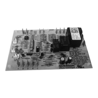
Details how the valve motor, thermostat, and auxiliary contacts work together.

Piping Diagrams and Considerations

Common Piping System Plans

Illustrates two common piping system plans (Plan 1 and Plan 2) for zone valve installation.

Leakage Characteristics

Informs about permissible leakage through the valve when closed.

Installation Procedures

Valve Body Mounting

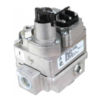
Instructions for mounting the valve body, including position and clearance requirements.

Head Assembly and Locking

Guidance on assembling the valve head to the body and ensuring secure locking.

O-ring Lubrication

Specifies acceptable lubricants for O-rings to prevent deterioration.

Piping Support

Recommends supporting piping with hangers on each side of the valve.

Wiring Instructions and Diagrams

General Wiring Guidelines

Recommends thermostat wire gauge and adherence to electrical codes.

Motor Operation Testing

Provides instructions for checking motor operation without a thermostat.

System Wiring Diagrams

Presents diagrams for systems where burner/circulator is independent of thermostat.

Internal Transformer Wiring

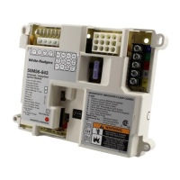
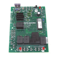
Shows wiring for systems using an internal transformer of relay control for zone valves.

Advanced Wiring Scenarios

Gas-Fired System Wiring

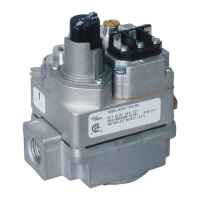
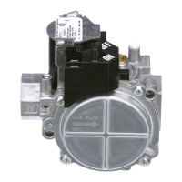
Details wiring for gas-fired systems using various relay controls (842A-16, 8F42A, 8F43A).

External Transformer Wiring

Wiring diagrams for systems requiring an external transformer for powering zone valves.

Oil-Fired System Wiring

Wiring configurations for oil-fired systems with different relay and control types.

Manual Operation and System Return

Manual Operator Usage

Explains how to use the manual operator during power failure or testing.

Valve Behavior on Power Resumption

Describes how the valve returns to thermostat command after power is restored.

Related product manuals