EasyManua.ls Logo

White Rodgers 36C03 Series User Manual

White Rodgers 36C03 Series
8 pages
To Next Page IconTo Next Page
Page #1 background imageLoading...
Page #1 background image
Pilot Gas Outlet:
Located at outlet end of the valve
Type of Gas
Suitable for all domestic heating gases
Pressure Rating: 1/2 lb. per sq. in.
Pressure Regulator Adjust Range (Typical, See
Control Label):
Natural Gas: 2.5 to 5.0" W.C.
LP Gas: 7.5 to 12" W.C.
Ambient Temperature: -40° to 175°F
Thermocouple:
(24V & 120V types): Use W-R Type HO6
(.750V Quick Drop Out Power Unit for
36D34 models only): Use W-R Type H19E
Pilot Generator (.750 volt types):
Use W-R Type G01A-32
Mounting: Any position except upside-down
PIPE SIZES/CAPACITIES
Pipe Size
(inches)
Capacity (BTU/hr) at
1” pressure drop across valve
1
2
” x
3
8
1
2
” x
1
2
1
2
” x
3
4
3
4
” x
3
4
100,000
230,000
230,000
280,000
162,000
372,600
372,600
453,600
Nat. Gas
(1000 BTU/cu. ft.,
64 Sp. Gr.)
LP Gas
(2500 BTU/cu. ft.,
1.53 Sp. Gr.)
INLET BOSS
UP OR DOWN
UPRIGHT
LEFT OR RIGHT
Upright, 90° from upright or vertical
NOTE: Control shown may not be identical
to replacement control.
ON
OFF
INSTALLATION INSTRUCTIONS
FAILURE TO READ AND FOLLOW ALL INSTRUCTIONS CAREFULLY BEFORE
INSTALLING OR OPERATING THIS CONTROL COULD CAUSE PERSONAL INJURY
AND/OR PROPERTY DAMAGE.
The 36C03, 36C13 and 36D34 complete gas controls
combine into a single compact package the functions of
3-position gas cock, pressure regulator, 100% shut-off
automatic pilot, and main operator. Separate models
are available for use on 24 VAC, 120 VAC and .750 VDC
systems. These controls can be mounted in any orientation
except upside down.
MODELS AVAILABLE
Model No. Voltage
36C03
36C03A
36C03U
36C13
36C13A
36C13U
36D34U
Current
.23 Amp
.035 Amp
DC
.23 Amp
.035 Amp
DC
DC
24 volts
120 volts
.750 volts
24 volts
120 volts
.750 volts
.750 volts
Gas
Nat.
Nat.
Nat.
LP
LP
LP
Nat./LP
OFF
PILOT
ON
ECO
Terminals
OFF
PILOT
ON
The 36C03 and 36C13 models are also available without
pressure regulator as a Model 36C10.
The 36D34 model is limited to .750 VDC applications and
is equipped with a "quick drop out" power unit for vented
gas hearth products.
Operator: Save these instructions for future use!
DESCRIPTION
SPECIFICATIONS
36C03, 36C10, 36C13 and 36D34
Combination Gas Valves
(24 Volt, 120 Volt and .750 Volt Models)
PART NO. 37-5781E
Replaces 37-5781D
1547white-rodgers.com
Question and Answer IconNeed help?

Do you have a question about the White Rodgers 36C03 Series and is the answer not in the manual?

White Rodgers 36C03 Series Specifications

General IconGeneral
BrandWhite Rodgers
Model36C03 Series
CategoryControl Unit
LanguageEnglish

Summary

Combination Gas Valves Product Information

Product Description

Details the features of the 36C03, 36C13, and 36D34 gas controls and their ECO terminals.

Available Models and Voltages

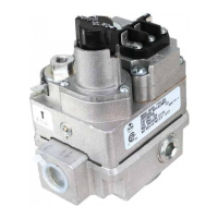
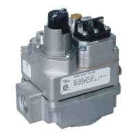
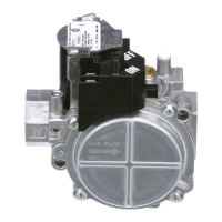
Lists the different model numbers, their voltage (24, 120, .750 VDC), and gas types.

Gas Valve Specifications

Pilot Gas Outlet and Type of Gas

Specifies the location of the pilot gas outlet and suitability for domestic heating gases.

Pressure Ratings and Adjustments

Details pressure rating, regulator adjust range for Natural and LP gas, and ambient temperature.

Thermocouple and Pilot Generator Requirements

Specifies required thermocouple and pilot generator types for different voltage models.

Mounting Orientation

Defines permissible mounting positions for the gas control valve.

Pipe Sizes and Gas Capacities

Provides a table of pipe sizes and their corresponding gas capacities (BTU/hr) for Natural and LP gas.

Gas Valve Installation Procedures

Pre-Installation Safety Warnings and Cautions

Crucial safety warnings and cautions to be followed before starting installation.

Main Piping Connections

Step-by-step guide for making main gas and electrical piping connections.

Pilot Gas Connection Installation

Instructions for installing the pilot gas tubing into the valve outlet.

System Wiring Diagrams

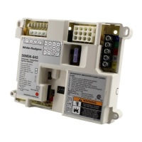
Provides wiring diagrams for .750 Volt, 24 Volt, and 120 Volt systems.

Energy Cut-Off (E.C.O.) and Thermocouple Connections

Guidance on connecting E.C.O. devices and thermocouple for reliable operation.

Pilot Generator Connection

Instructions for connecting the pilot generator for .750 VDC models.

Pilot Gas and Pressure Regulator Adjustments

Procedures for adjusting pilot gas pressure and main pressure regulator settings.

Pilot Lighting and Operation

Pilot Lighting Safety Precautions

Essential safety steps and warnings to follow before lighting the pilot.

Pilot Lighting Instructions

Step-by-step guide for safely lighting the pilot flame.

Turning Off Gas Supply to Appliance

Procedure for turning off the gas supply to the appliance for service or shutdown.

Related product manuals