
B
Brenda JamesAug 15, 2025
What to do if White Rodgers Control Unit has open fuse?
- JjoannemoonAug 16, 2025
If the White Rodgers Control Unit has an open fuse, find and repair the 24V fault, then replace the fuse.
What to do if White Rodgers Control Unit has open fuse?
If the White Rodgers Control Unit has an open fuse, find and repair the 24V fault, then replace the fuse.
How to fix Low Flame Current Sense on White Rodgers Control Unit?
If you are experiencing a low flame current sense with your White Rodgers Control Unit, check the flame quality and clean or replace the flame sensor.
What to do if White Rodgers Control Unit detects flame when no flame should be present?
If the White Rodgers Control Unit detects a flame when no flame should be present, check the gas valve for proper operation, and inspect the gas valve and safety limit wiring.
What to do if Ignitor Open Failure occurs on White Rodgers Control Unit?
If the White Rodgers Control Unit shows an Ignitor Open Failure, replace the failed ignitor.
What to do if Pressure Switch is stuck closed on White Rodgers Control Unit?
If the Pressure Switch is stuck closed on your White Rodgers Control Unit, replace the failed pressure switch.
How to fix Line Frequency Error / Internal Fault on White Rodgers Control Unit?
If the White Rodgers Control Unit displays a Line Frequency Error or Internal Fault, verify the 60 Hz line frequency and replace the control if necessary.
What causes Ignitor Relay Fault on White Rodgers Control Unit?
An Ignitor Relay Fault on the White Rodgers Control Unit indicates an internal ignitor relay failure, requiring replacement of the control.
How to resolve Twinning Error on White Rodgers Control Unit?
If a Twinning Error occurs on the White Rodgers Control Unit, validate the twin configuration for both units.
How to fix NFC Connectivity Error on White Rodgers Control Unit?
If you encounter an NFC Connectivity Error on the White Rodgers Control Unit, power cycle the control and retry.
What causes Lockout - Gas Valve Off on White Rodgers Control Unit?
Lockout - Gas Valve Off on White Rodgers Control Unit is caused by a gas valve relay internal error, replace control to solve the problem.
Compliance with warnings prevents injury or property damage. Installation by qualified professionals is required.
Avoid exceeding voltage, protect from water, label wires, and route away from flame to prevent fire risks.
Ensure proper grounding, disconnect power before servicing, and maintain 1/4" clearance from grounded metal.
Shut off main gas supply to the appliance until installation is fully complete to prevent explosion.
Table detailing configuration menu items, options, and factory default settings for the control.
Guidance on physically mounting the control unit using provided hardware and OEM patterns.
Cross-reference list for replacing 80V ignitors with the included 120V HotRod ignitor.
Notes on using the control with specific Goodman Hybrid furnace systems and staging logic.
How to connect and operate the control with 1 or 2 stage AC/HP systems and defrost cycles.
Details on how the control supports dehumidification via thermostat DHUM terminal.
Explanation of the control's automatic configuration for OEM applications and wiring.
Configuring blower motor type (PSC/ECMx) and speed settings for optimal furnace operation.
Instructions for bypassing rollout switch inputs for specific furnace brands like Trane and York.
Handling Trane/American Standard spade terminal blocks for wiring connections.
Requirement for a specific flame sensor kit on older Rheem/Ruud models.
Guidance on removing old universal controls and their adapter harnesses.
Understanding the 7-segment display codes during heating, cooling, or fan operation.
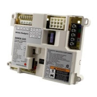
Tips for identifying and connecting OEM wiring harnesses to the 50M56X-843 connectors.
Wiring diagrams for 6-socket Nordyne/Nortek and Rheem/Ruud configurations.
Wiring diagrams for 4-pin Goodman/Amana and Trane/American Standard configurations.
Wiring diagrams for 4-socket Lennox/Allied Air and 6-pin inline Goodman/Amana.
Wiring diagrams for 2-pin Carrier/Bryant/Payne/ICP configurations.
Wiring for 9-socket Goodman/Amana and alternative configurations.
Wiring for 9-socket Nordyne/Nortek/Rheem/Ruud configurations.
Wiring diagrams for 12-pin configurations including Goodman/Amana Hybrid and Lennox/Allied Air.
Wiring diagrams for 10-pin inline Trane/American Standard and alternative configurations.
Detailed wiring information for 11-pin inline Carrier/Bryant/Payne/ICP, including specific pinouts.
Overview of thermostat wire connections and color coding for various terminals.
Table of 7-segment display codes and their corresponding conditions and troubleshooting steps.
Explanation of LED displays for various operational states, errors, and diagnostic codes.
Procedures for recalling and resetting stored fault codes on the control.
Methods for resetting the control, including automatic reset and manual power cycling.
Information on measuring flame current using the 7-segment display and test pins.
How to enter and utilize the self-test mode to diagnose furnace components.
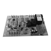
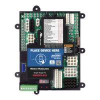
| Model Number | 50M56X-843 |
|---|---|
| Type | Integrated Furnace Control |
| Voltage | 24V AC |
| Voltage Rating | 24V AC |
| Ignition Type | Direct Spark Ignition |
| Compatibility | Compatible with most furnace models |
| Display | LED |
| Features | Diagnostic LEDs |