EasyManua.ls Logo

White Rodgers 36C03 User Manual

White Rodgers 36C03
24 pages
To Next Page IconTo Next Page
Page #1 background imageLoading...
Page #1 background image
FAILURE TO READ AND FOLLOW ALL INSTRUCTIONS CAREFULLY
BEFORE INSTALLING OR OPERATING THIS CONTROL COULD CAUSE
PERSONAL INJURY AND/OR PROPERTY DAMAGE.
The 36C03 and 36C10 series valves are designed
to meet requirements for use on standing con-
tinuous pilot systems. 36C03 combination models
include a pressure regulator, 100% shut-o auto-
matic pilot, and main operator. 36C10 models do
not have a pressure regulator.
36C Inst
Voltage
# of
Stages
Open
Characteristics
Standing
Pilot
Intermittent Pilot
Proven Pilot
HSI DSI
36C03/36C10 24V 1 Fast Yes No No No
36C03U 750mV 1 Fast Yes No No No
36C03A 120V 1 Fast Yes No No No
PRESSURE REGULATOR ADJUSTMENT RANGE
EXCLUDING 36C10
Gas Type
Single Stage
Natural Gas 2.5–5.0
LP Gas 7.5–12.0
SPECIFICATIONS
DESCRIPTION
INSTALLATION INSTRUCTIONS
36C03, 36C03A, 36C03U & 36C10
Standing/Continuous Pilot Combination Gas Valve
OFF
PILOT
ON
ECO
Terminals
OFF
PILOT
ON
Pilot Gas Outlet:
Located at outlet end of the valve
Type of Gas: Suitable for all domestic heating
gases
Ambient Temperature: -40º to 175ºF
Pressure Rating: 14" W.C. (1/2 PSI) Max
Voltage/Current: 36C03U – 750mV
36C03/36C10 – 24V/0.23A
36C03A – 120V/0.035A
CONTENTS
Description ........................................................................... 1
Specications ....................................................................... 1
Precautions ........................................................................... 2
Installation ............................................................................ 3
System Wiring
Adjustment .......................................................................... 5
Pressure Regulator Adjustment
Lighting Instructions ............................................................ 6
Contents French ........................................................................ 9
Contents Spanish.....................................................................17
PIPE SIZES/CAPACITIES
Pipe Size
(inches)
Capacity (BTU/hr) at
1" pressure drop across valve
Range of Regulation
Excluding 36C10 Non-Regulated
Nat. Gas
(1000 BTU/cu. ft., 64
Sp. Gr.)
LP Gas
(2500 BTU/cu. ft.,
1.53 Sp. Gr.)
AGA Std. Nat. Gas
0.64 Sp. Gr.
(1,000 BTU/cu. ft.)
LP Gas
1.53 Sp. Gr.
(2,500 BTU/cu. ft.)
1/2" x 3/8"
100,000 162,000 15,000 - 100,000 15,000 - 162,000
1/2" x 1/2"
230,000 372,600 30,000 - 290,000 30,000 - 469,000
1/2" x 3/4"
230,000 372,600 30,000 - 290,000 30,000 - 469,000
3/4" x 3/4"
280,000 453,600 50,000 - 400,000 50,000 - 648,000
Parts and Accessories:
Conversion Kit
• F92-0659 Nat. to LP Gas (7.5" to 12.0" W.C.)
• F92-0737 Nat. to LP Gas (Non-regulated)
• F69-0727 1/4" brass compression tting for pilot
line connection
Thermocouple (24V & 120V types):
Use W-R Type H06
Pilot Generator (.750 volt types):
Use W-R Type G01A-32
www.white-rodgers.com
www.emersonclimate.com
PART NO. 37-7349B
Replaces 37-7349A
1429
f i r e - p a r t s . c o m
Question and Answer IconNeed help?

Do you have a question about the White Rodgers 36C03 and is the answer not in the manual?

White Rodgers 36C03 Specifications

General IconGeneral
BrandWhite Rodgers
Model36C03
CategoryControl Unit
LanguageEnglish

Summary

Product Overview and Specifications

Gas Valve Model Descriptions

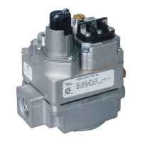
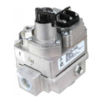
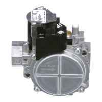
Overview of 36C03, 36C03A, 36C03U & 36C10 valve models and their features.

Technical Specifications and Capacities

Details on valve capacities, pressure regulation ranges, pipe sizes, and parts/accessories.

Safety Precautions

General Safety Warnings

Critical warnings regarding fire, explosion, injury, shock, and property damage from improper installation/operation.

Gas Piping and Handling Precautions

Guidelines for safe gas piping, leak detection, and handling of damaged or water-exposed valves.

Operational and Electrical Cautions

Cautions related to circuit voltage, testing methods, water exposure, and cleaning gas piping.

Installation Procedures

Main Piping Connections

Instructions for connecting the main gas supply piping, including threading, sealing, and tightening.

Pilot Gas Connection

Steps for correctly installing the pilot gas tubing fitting and securing the connection.

System Wiring and Connections

Wiring for 24V Models

Wiring diagrams for 36C03 (24 VAC) with E.C.O. switch or supplementary limit.

Wiring for 750mV Millivolt Pilot Generator

Wiring instructions for the 750 millivolt pilot generator system, including thermostat and pilot generator hookup.

Wiring for 120V Models

Wiring diagrams for 36C03A (120 Volt) connecting to line voltage thermostats or operating controls.

Adjustment and Setup

Energy Cut Off (E.C.O.) Connection

How to connect E.C.O. terminals to the furnace E.C.O. device or jumper them.

Thermocouple and Pilot Generator Connections

Proper methods for connecting thermocouples and pilot generators to the gas valve.

Pilot Gas Pressure Adjustment

Steps to adjust pilot gas pressure for optimal pilot flame performance.

Pressure Regulator Adjustment

Procedure for adjusting the gas valve's internal pressure regulator.

Pilot Lighting and Operation

Pilot Lighting Procedure

Step-by-step guide to safely lighting the pilot flame, including safety checks and troubleshooting.

Turning Off Gas to Appliance

Instructions on how to safely shut off the gas supply to the appliance for servicing.

Related product manuals