PAGE 3 CONTAINS WIRING HARNESS AND
BLOWER CONNECTION INSTRUCTIONS FOR
ALL APPLICATIONS AND IMPORTANT OEM
REPLACEMENT INSTRUCTION FOR:
● TRANE / AMERICAN STANDARD
● RHEEM / RUUD
● BRYANT / CARRIER / DAY & NIGHT / PAYNE
INSTALLER MUST READ
www.white-rodgers.com
www.emersonclimate.com
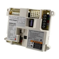
50M56U-843
Universal Single Stage
HSI Integrated Furnace Control Kit
INSTALLATION INSTRUCTIONS
FAILURE TO READ AND FOLLOW ALL INSTRUCTIONS
CAREFULLY BEFORE INSTALLING OR OPERATING
THIS CONTROL COULD CAUSE PERSONAL INJURY
AND/OR PROPERTY DAMAGE.
DESCRIPTION
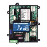
The 50M56U-843 kit is a Universal Single Stage HSI Integrated
Furnace Control that employs a microprocessor to continually
monitor, analyze, and control the proper operation of the gas
burner, inducer, and fan.
The kit contains:
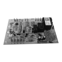
• 50M56-843IgnitionControlModule
• 21D64-2IgnitorKit
• SetofInterconnectHarnesses
Installation should be done by a qualified heating and air
conditioning contractor or licensed electrician.
If in doubt about whether your wiring is millivolt, line, or low
voltage, have it inspected by a qualified heating and air
conditioning contractor or licensed electrician.
Donotexceedthespecicationratings.
All wiring must conform to local and national electrical codes
and ordinances.
This control is a precision instrument, and should be handled
carefully. Rough handling or distorting components could
cause the control to malfunction.
Following installation or replacement, follow manufacturer’s
recommended installation/service instructions to ensure
proper operation.
PRECAUTIONS
PART NO. 37-7042C
Replaces37-7042B
1103
Do not short out terminals on gas valve or primary
control. Short or incorrect wiring may damage the
thermostat.
Failure to comply with the following warnings could result
in personal injury or property damage.
FIRE HAZARD
• Donotexceedthespeciedvoltage.
• Replaceexistingcontrolwithexactmodeland
dash number.
• Protectthecontrolfromdirectcontactwithwater
(dripping, spraying, rain, etc.).
• Ifthecontrolhasbeenindirectcontactwith
water, replace the control.
• Labelallwiresbeforedisconnectionwhen
servicing controls. Wiring errors can cause
improper and dangerous operation.
• Routeandsecurewiringawayfromame.
SHOCK HAZARD
• Disconnectelectricpowerbeforeservicing.
• Ensureproperearthgroundingofappliance.
• Ensureproperconnectionoflineneutralandline
hot wires.
EXPLOSION HAZARD
• Shutoffmaingastoapplianceuntilinstallation
is complete.
CONTENTS
Description ...................................................................1
Precautions ..................................................................1
Specifications ..............................................................2
Installation ...................................................................2
Mounting & Wiring
Operation ..................................................................... 6
Troubleshooting ........................................................... 8
50M56-843
21D64-2