WHITTAKER CONTROLS, INC.
A MEGGITT PLC COMPANY
MAINTENANCE MANUAL
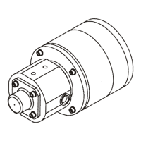
GAS VENT VALVE
C422425 • C422685 • C422695 • C422705 • C423095 • C423155
INDUSTRIAL PRODUCTS GROUP Revision 1.1 10/15/2004 Page 15
FAULT ISOLATION
1. General
Make sure that the electrical power is off before removing the
terminal cover or touching the electrical wires.
Assurez-vous que le courant électrique est au loin avant d'en-
lever la couverture terminale ou toucher les fils électriques.
This section contains specific checks required to fault isolate the gas vent valve during service. It is
assumed that the valve has been reported inoperative or has malfunctioned during operation.
2. Fault Isolation
A. Make sure that the electrical power is turned off and locked out.
B. Remove the screws and washers securing the terminal cover to the terminal housing, and re-
move the terminal cover.
C. Verify the electrical connections at the valve and the field wiring are correct. Refer to Figure 2
for the electrical schematic diagram.
D. Make sure that all of the wiring connections are secure and that there are no damaged wires.
E. If the wiring connections are all correct and secure, and the valve still will not operate, perform
isolation in accordance with the following paragraphs.
3. Solenoid Coil Resistance
A. Disconnect the wires connected to terminals 1 and 2.
B. Using an ohmmeter, measure the resistance between terminals 1 and 2. The resistance must
be 17 to 21 ohms.
C. If the resistance is not within the specified range, the solenoid coil is damaged. Replace the
valve. Return the failed valve to Whittaker Controls for repair.