WHITTAKER CONTROLS, INC.
A MEGGITT PLC COMPANY
MAINTENANCE MANUAL
GAS VENT VALVE
C422425 • C422685 • C422695 • C422705 • C423095 • C423155
INDUSTRIAL PRODUCTS GROUP Revision 1.1 10/15/2004 Page 11
INSTALLATION
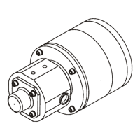
1. General
This section contains information on installation and interfacing of the gas vent valve. Refer to Figure
3 for key dimensions.
2. Inspection
Prior to installation, visually inspect the valve for shipping damage and general condition. Make sure
that there are no missing parts, loose fittings or fasteners, or any other obvious defects.
DO NOT OPEN WHEN AN EXPLOSIVE ATMOSPHERE MAY BE
PRESENT.
NE VOUS OUVREZ PAS QUAND UNE ATMOSPHÈRE EXPLOSIVE
PEUT ÊTRE PRÉSENTE.
Make sure that the electrical power is off before removing the
terminal cover or touching the electrical wires.
Assurez-vous que le courant électrique est au loin avant d'en-
lever la couverture terminale ou toucher les fils électriques.
3. Gas Inlet and Outlet Ports
The gas inlet and gas outlet connection ports are internally threaded 1/2-14 ports.
4. Electrical Wiring
A. To gain access to the terminal block, remove the screws and washers and the terminal cover.
B. The electrical wiring entry into the terminal housing must be accomplished using methods ap-
proved by the local certification agencies (i.e., Cenelec, CSA, FM, etc.). Connect the conduit
to the 1/2-14 NPT conduit/entry port for using a suitable conduit connector. Torque the conduit
connector to 450 to 500 pound-inches (51 to 56 Nm).
C. All customer field wiring conductors must be 18 AWG minimum.