2010 Edition 1 Page 16
6.0: TORQUE SETTINGS
Torque explained: If no suitable Torque Wrench is available a Torque of 5 lbf.ft can be obtained by ap-
plying a force of 5lb, with a Spring Balance, to the end of a spanner, 1 Foot in length.
IMPORTANT: For all other torque settings, refer to the specific manufacturers information
bundled with this manual, or alternatively, refer to the specific manufacturers website for
further information.
7.0: NOTES
WHYTE Service Manual
Whyte 19 Dropout System Nm lbs.ft
M6 x 14mm Pivot Screw 13 - 15 9.5 - 11
M6 x 16mm Clamping Screws 13 - 15 9.5 - 11
2010 Edition 1 Page 5
WHYTE Service Manual
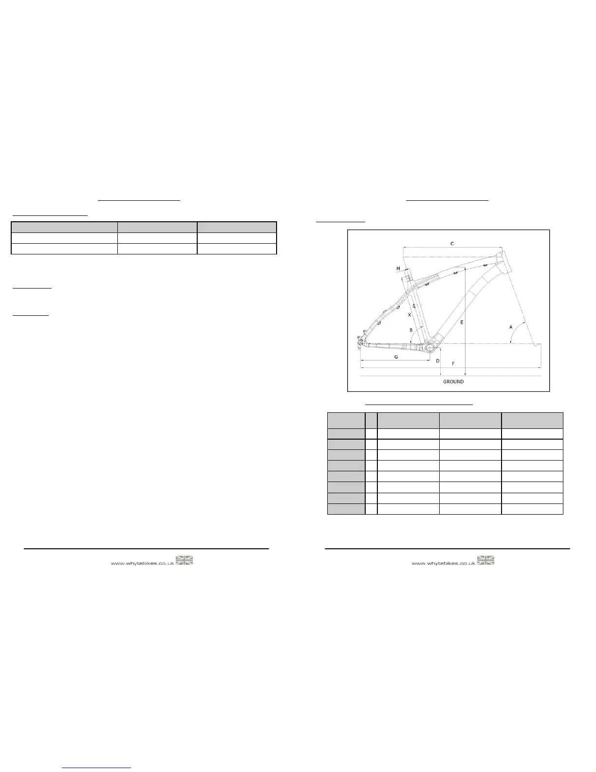
2.0: GEOMETRY
Frame Size
Small Medium Large
Head Angle 67.7 - 68.2° 67.7 - 68.2° 67.7 - 68.2°
Seat Angle 72.2 - 72.7° 72.2 - 72.7° 72.2 - 72.7°
Top Tube 565.1mm 584.5mm 609.6mm
BB Height* 319.7mm - 325.7mm 319.7mm - 325.7mm 319.7mm - 325.7mm
Stand Over 775mm 797mm 823mm
Wheel Base 1065.3mm - 1082.5mm 1085.2mm - 1102.4mm 1111.1mm - 1128.3mm
Chain Stay 415mm - 435mm 415mm - 435mm 415mm - 435mm
Seat Post 30.9mm 30.9mm 30.9mm
X
A
B
C
D
E
F
G
H
2.1: WHYTE 19 TRAIL, TI & STEEL
Note:
Geometry shown here is ’Showroom’ i.e. without rider aboard the bicycle. ’With Sag’ geometry is with rider after correct
sag is set at the front. Please refer to suspension set up for information on how to achieve the correct sag of the fork.
* BB height with Ø677mm tyres fitted (2.25” / 54-559)
Fig.1:
Geometry