14
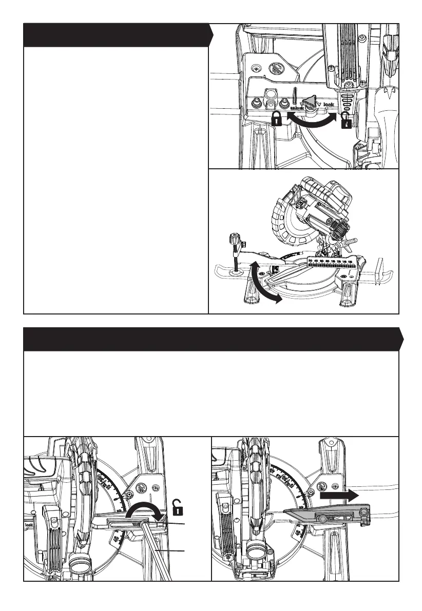
3. BEVEL LOCK (SEE FIG. G1-G4)
The bevel lock is used to set the blade at the desired bevel angle. The mitre saw bevel cuts from 0° to 45° to the left (the
saw blade is facing to the operator). To adjust the bevel angle, follow the steps below:
1) Loosen the locking bolt (d) using the M5 hex key provided located on the extended fence for bevel cutting. Pull the
extended fence outwards to its farthest position. (See Fig. G1, G2) Tighten the locking bolt again to lock the fence.
2) Loosen the bevel lock knob by turning it anti-clockwise and move the saw head to the left (the saw blade is facing to
the operator) to a desired bevel angle (between 0° and 45°). Tighten the bevel lock knob by turning it clockwise.
NOTE: Assembly the work clamp on the right side before adjusting into bevel cut mode.
The mitre saw cuts from 0° to 45° only in the left side (the
saw blade is facing to the operator).
To adjust the mitre angle, rst loosen the mitre table
lock knob by turning it anti-clockwise. Then hold the
rotating mitre table handle and move the handle to the
left in order to adjust the rotating mitre table to a desired
angle. Align the pointer with the mitre angle scale marked
on the table. After that, tighten mitre table lock knob
by turning it clockwisethe to lock the mitre table in the
required mitre angle.
The rotating mitre table features positive click stops at
0°, 15°, 22.5°, 30° and 45° for quick setting of common
mitre angles.
2. MITRE TABLE LOCK (SEE FIG. F1, F2)
Fig. F2
d
27
Fig. F1
Fig. G1
Fig. G2