19
h
Remove the plug from the socket before carrying out any adjustment, servicing or maintenance.
There are no user serviceable parts in your power tool. Never use water or chemical cleaners to clean your power tool.
Wipe clean with a dry cloth. Always store your power tool in a dry place. Keep the motor ventilation slots clean. Keep
all working controls free of dust. Occasionally you may see sparks through the ventilation slots. This is normal and will
not damage your power tool. If the supply cord is damaged, it must be replaced by the manufacturer, its service agent or
similarly qualied persons in order to avoid a hazard.
MAINTENANCE
While the machine has been factory set, it is advisable
that the 0
o
setting of the rotary table and the 90
o
perpendicular setting of the tilt be checked, as these
positions may have moved in transit.
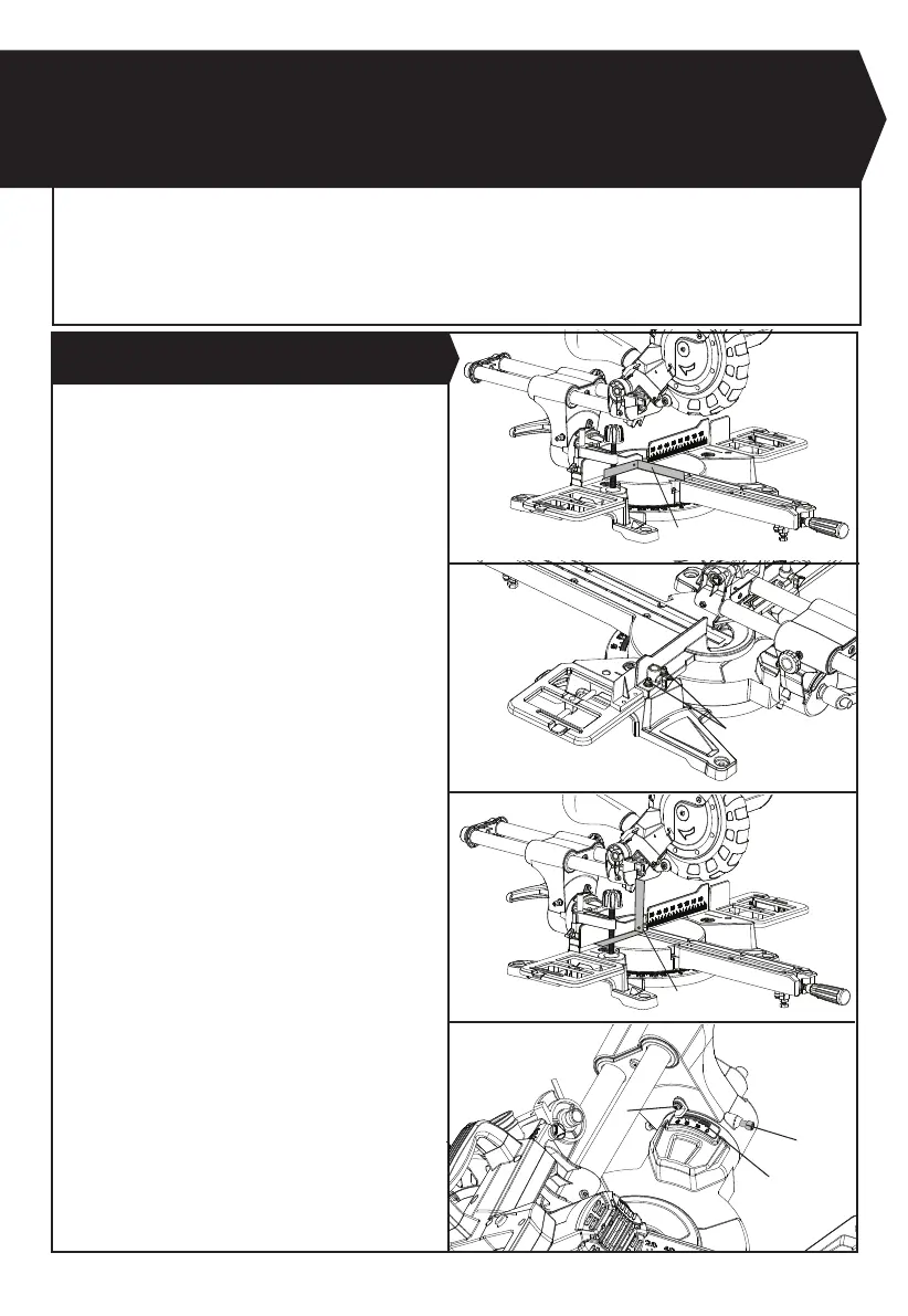
To conrm the 0
o
rotating mitre table setting, set the
rotating mitre table at 0
o
and tighten the mitre table lock
latch. Check that the angle between the straight guide
and the blade is 90° using a tri-square (h) (not supplied)
as shown in Fig. S1. If the angle requires adjustment,
loosen the locking bolts (i) for straight guide, and align
the fence against the tri-square.
Re-tighten the locking bolts (i) for straight guide.
Similarly, check that the angle of the blade to the face of
the rotary table is 90°. If necessary, adjust the tilt angle
of the saw head at the 90
o
position: loosen the bevel
lock lever and adjust the 0° bevel adjustment screw (j)
to bring the saw blade into alignment with the square.
Loosen the head screw (k) holding the pointer of the
bevel scale and adjust the position of the pointer so that
it accurately indicates zero on the scale. Retighten the
head screw (k). Retighten the bevel lock lever and the 0°
bevel adjustment screw (j).
1. PRECISION SETTING OF ANGLES(SEE FIG. S1-S4)
h
i
j
k
28
Fig. P
Fig. Q
Fig. S4
Fig. S1
Fig. S2
Fig. S3