6
12. FLUE INSTALLATION
Positioning:
• The water heater MUST be installed so that the terminal is exposed to the external air.
• It is important that the position of the terminal allows free passage of air across it at all times.
• It is ESSENTIAL TO ENSURE, that products of combustion discharging from the terminal cannot re-enter the
building, or vehicle, through ventilators, windows, or other sources of natural air infiltration, such as other flues
etc, with the exception of doors, but not the opening windows thereof. The minimum acceptable dimensions
from the terminal to obstructions and ventilation openings must be as detailed in section 2.
Installing the flue system:
IMPORTANT
The standard horizontal flue kit supplied with the RSW10KL is part number RSWFK1M. This kit provides for 1
meter of flue length and one 90
0
elbow. Note: DO NOT INSTALL THIS APPLIANCE WITH MORE THAN ONE 90
0
Elbow (Bend) and more than 1.0 metre of flue length.
Never use a flue kit not specifically approved for use with this appliance.
NOTE: Where the home is pre-installed with the RSW10KL please consult the home manufacture for
replacement part numbers.
NOTE: The inner flue pipe of the terminal must be cut
accurately and must always be 100 mm longer than the outer
flue in order to ensure correct location in the terminal and
elbow. NOTE: The outer pipe has two holes at one end to
fix the terminal always cut the pipe at the opposite end to
these two holes.
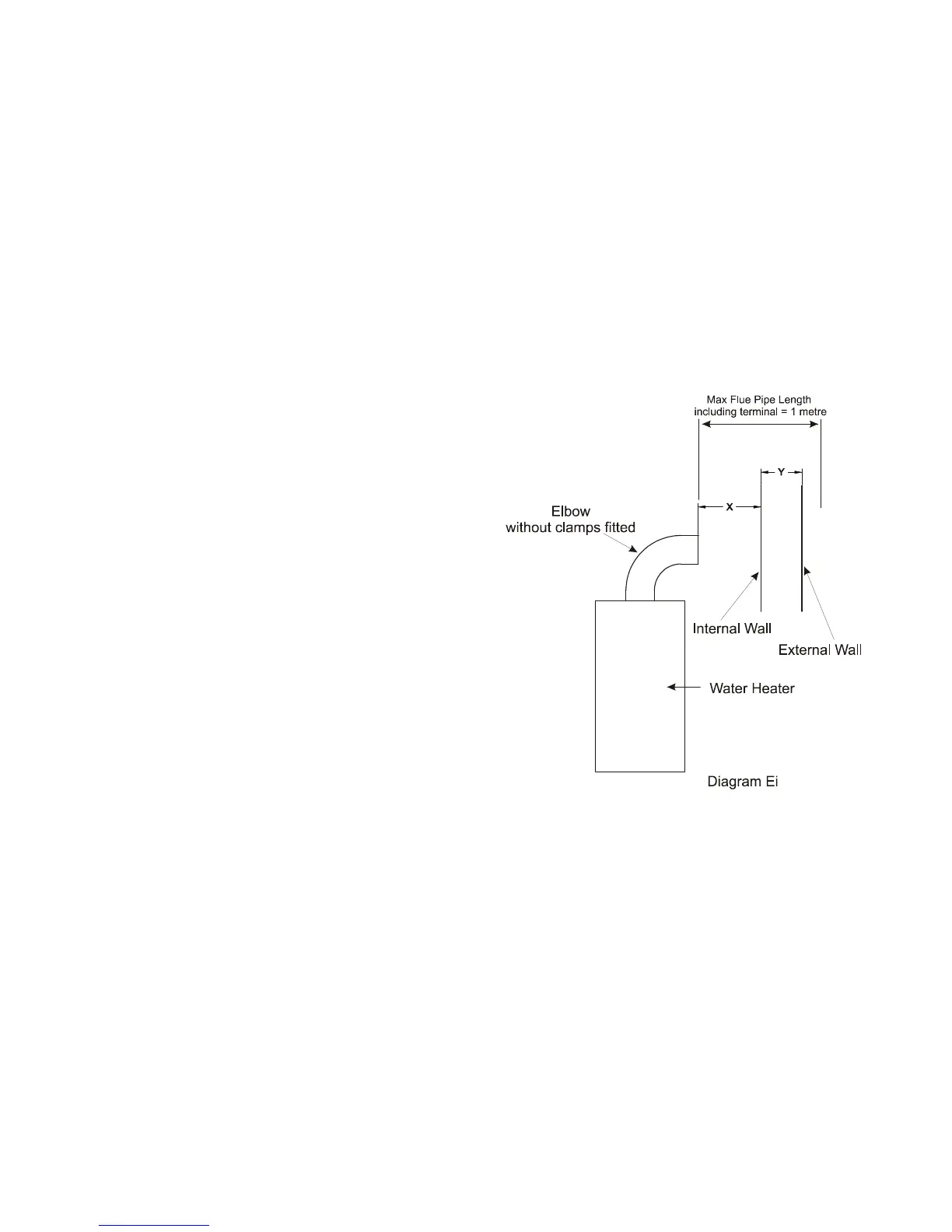
To calculate the correct length of the outer flue use the
following formula and refer to diagram Ei
Formula: dimension X + Y + 20 mm (Note Dimension X is
the distance between the inner wall of the home and the
end of the elbow without the sealing collar attached; in
the case of rear flue installation the appliance should be
fitted with installation Kit RSWFIX01 if this kit is used
then the dimension X = 10mm.)
For calculating the inner flue lengths use the overall length of
the outer flue liner when cut to size and add 100mm.
Two sealing collars are provided to seal the external pipe
against the internal and external wall.RSWSC01.
The flue assembly must be installed with a slight downwards
incline of 2
0
towards the terminal to prevent the ingress of rain water, which may damage the heater. See diagram Eii.
Terminal Guard: if the position on the outlet terminal is less that 2 meters above ground level it is recommended that
a terminal guard be fitted.