12 User and service manual
WARNING
Safety precautions
a) These pumps are designed for trained personnel only, who must know the
refrigeration fundamentals, cooling systems, refrigerants and the possible damage
that pressurized equipment may cause.
b) Carefully read the instructions contained in this manual; strict observance of the
procedures described is fundamental for the operator’s safety, the perfect state of the
pump and constant performances as declared.
c) Wear suitable protections like safety glasses and gloves; contact with refrigerant may
cause blindness and other personal injuries.
d) Do not operate near open ames and hot surfaces; high temperatures decompose
the refrigerant releasing toxic and caustic substances which are hazardous for the
operator and the environment.
e) Avoid skin contact; the low boiling temperature of the refrigerant (about -40°C) can
cause freezing.
f) Avoid breathing refrigerant vapors
g) Always make sure that the pump is connected to a suitably protected mains supply
provided with an efficient earth connection
h) Even if the pump’s temperature never reaches high values during evacuation, make
sure to place the pump so that it can never cause damages to the operator, such as
small burns.
i) Operate the pump only in locations with suitable ventilation and a high number of air
changes.
j) Before disconnecting the pump, make sure that the cycle has been completed and
that all valves are closed in order to avoid release of refrigerant to the atmosphere.
k) Never ll any tank with liquid refrigerant to more than 75% of its maximum capacity.
l) When the unit will not be used for a long period of time, disconnect the power supply
cord.
m) During operations avoid release of refrigerant to the environment; this precaution is
required by international environmental standards and is essential to avoid difficult
leak detection in a refrigerant polluted environment.
!
ENGLISH
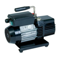
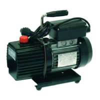
1. Introduction to WIGAM high vacuum pumps
Wigam high vacuum pumps are rotary vane type and lubricated by oil injection, single and dual stage, complete
with gas ballast valve to remove residual condensable gases.
Each stage is equipped with a rotor mounted on a shaft, which is directly connected to the electric motor without
joint; in the dual stage pumps, the two rotors are connected to one another in series, in order to reach the best
vacuum possible.
1.1 General performance and technical data
Pump model
DIP401 RS3D RS4D DIP402 RS9D RS15D RV25B
Swept volume l/min 80 46 66 80 180 250 440
Vuoto nale mbar 6x10
-2
1x10
-2
1x10
-2
1x10
-2
1x10
-2
1x10
-2
1x10
-4
Nominal power W 180 120 120 240 370 550 550
Rotation rate giri/min 2.800 2.800 2.800 2.800 1.450 2.800 1.450
Oil charge cc 210 300 225 300 450 400 1.000
Working temperature °C 0/+40 0/+40 0/+40 0/+40 0/+40 0/+40 0/+40
Storage temperature °C -25/+50 -25/+50 -25/+50 -25/+50 -25/+50 -25/+50 -25/+50
Weight kg 7,2 6,4 6,5 8,2 12,00 16,00 29,50
Supply* 230/1/50-60 230/1/50-60 230/1/50-60 230/1/50-60 230/1/50-60 230/1/50-60 **
*Other supplied on request
* Standard supply 230/1/50-60 or 380/3/50
1.2 Gas ballast valve
Wigam vacuum pumps are equipped with a gas ballast valve (*), to keep open for about 3 minutes during
evacuation; the gas ballast valve allows a good pump starting and prevents polluted vapors from condensing in
the lubricant.
2. Installation
The pump is supplied without oil charge; before its rst use, it is necessary to ll the pump with the correct quantity
and type of oil suggested by the manufacturer.
2.1 Oil lling
When lling the oil or checking the oil level, the pump must be turned off.
The pump is supplied without oil charge; before its rst use, it is necessary to ll the pumps with the correct quantity
and type of oil suggested by the manufacturer.
A different lubricant reduces the performances and can irreversibly damage its mechanical parts.
A bottle of 400cc mineral oil is supplied with the pump.
To ll the oil into the pump, proceed as follows:
a) unscrew the charging cap (situated on top of the pump)
b) slowly ll in the oil up to the middle of the sight glass (situated on the side of the pump)
c) screw the charging cap
To avoid excessive lling, we suggest to spill the oil into a graduated bottle rst; in this way it is easy to check the
correct quantity.
In case of excessive lling, it is necessary to empty the pump and repeat the oil lling procedure.
2.2 Suction connection
A shorter and wider hose (as well as a straight “path”) reduces time to perform evacuation.
On request, the suction connection can be equipped with a solenoid valve (a solenoid valve is standard equipment on
model RV25B) to prevent the lubricant from owing back from the pump to the circuit in case of electric power cut.
2.3 Vapors discharge
The pump can run without any discharge connection; when large volume circuits must be evacuated or in case the
pump is frequently turned on and off, we suggest to replace the standard cap with an oil extracting lter complete
with an oil receiver; the oil discharged during functioning is collected by the lter and drops into the oil receiver.
2.4 Electric connection
User and service manual 13
WARNING
Always let the pump discharge connection free; ist obstruction can cause dangerous overpressures
inside the pump’s oil sump.
WARNING
Do not pollute environment with the lubricant; it is a special waste and must be disposed of according
the the current regulations.