INSTRUCTION MANUAL
NI-221WE
Rev. 5 12/16
3 of 9
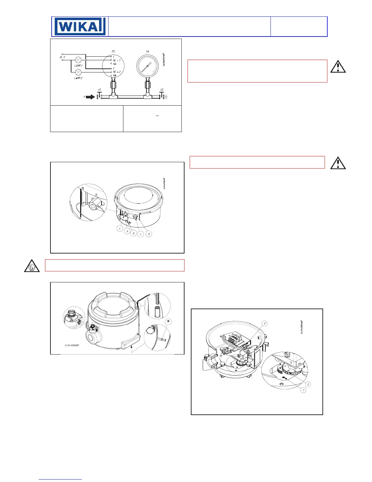
Fig. 3 - Calibration circuit
PS - Pressure switch
CA - Test gauge
V1 - Inlet valve
V2 - Discharge valve
P - Pressure source
Test fluid:
air for P < 10 bar
water for P > 10 bar
6.1
PRELIMINARY OPERATIONS
6.1.1
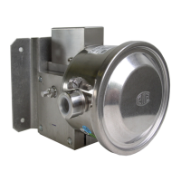
Weatherproof pressure switches (Model MW)
Remove the blocking device fixed to the side of the instrument
case (Fig. 4).Remove the cover by rotating it in an anticlockwise
direction.
Fig. 4 - Weatherproof pressure switch blocking device
a - Plumbing wire
b - Plumbing
c - Nut
d - Blocking bracket
6.1.2
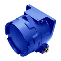
Flameproof pressure switches (Model MA)
CAUTION: do not open the cover of pressure switches when en-
ergized, in explosive atmospheres.
Loosen the locking headless screw situated on the cover using a
1,5 hexagonal key then unscrew the cover (fig.5).
Fig. 5 - Flameproof pressure switch blocking device
6.2
CALIBRATION CIRCUIT AND OPERATIONS
Prepare the calibration circuit as indicated in Fig.3.
The warning lamps should be connected to contact 1 or 2 in the
NO or NC position according to the required contact action.
Connection of C and NO terminals
• If the circuit is open at the working pressure, the switch closes
the circuit as the pressure increases when the desired value is
reached.
• If the circuit is closed at the working pressure, the switch opens
the circuit as the pressure decreases when the desired value is
reached.
Connection of C and NC terminals
• If the circuit is closed at the working pressure, the switch opens
the circuit as the pressure increases when the desired value is
reached.
• If the circuit is open at the working pressure, the switch closes
the circuit as the pressure decreases when the desired value is
reached.
The pressure switch must be mounted in the normal installation
position, i.e. with the pressure connection pointing downwards.
Avoid forcing the elastic support of the microswitch by hand or with
tools. This could affect the instrument functioning.
CAUTION: if the switch is of the kind with adjustable dead band
(letter R in the contact codes) before proceeding with the following
operations it is necessary to proceed with the adjustment of the
dead band.
Increase the pressure in the circuit up to the desired set point value
for the first microswitch. Use a wide bladed screwdriver, as indi-
cated on the label, turn the screw until the relative lamp turns on
(or turns off).
- If the instrument is equipped with only one contact the calibration
is complete.
- If it is equipped with two contacts continue in the following man-
ner. Vary the pressure until the desired set point value for the sec-
ond microswitch is reached. Act on the adjustment screw of the
second contact.
Repeat calibrating operations on the first contact, then on the sec-
ond contact, until the required set point accuracy is obtained. This
is necessary due to the reciprocal influence which the micro-
switches have on the sensitive element of the instrument.
CAUTION: if the two set point are different they must be different
for much of 5% of the adjustable span.
6.3
CALIBRATION OF INSTRUMENT WITH SENSING
ELEMENT H AND G
The pressure switches equipped with sensor H and G, are
instruments with a piston sensing element. To perform an high
accuracy calibration, due to the sensing element, it is necessary to
adjust the set point by varying the pressure from the normal
working pressure of operation to the set point.
6.4
CHECK OF SET POINT
Generate the normal working pressure and wait the pressure sta-
bilisation. Vary the pressure into the circuit and record the set point
value. Write the set point values on the adhesive label.
Note: the repeatability should be checked verifying for three times
the set point (Pi) starting always from the same pressure value
(Pw). The pressure cycle should be slowly to give the possibility to
record the set point with accuracy.
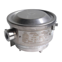
6.5
ADJUSTMENT OF DEAD BAND (LETTER R ON THE
MODEL CODE)
The dead band can be adjusted only on the instrument is equipped
with a microswitch, which allows adjusting (Letter R on the model
code). Adjustment may be obtained by rotating the wheel placed
on the microswitch (Fig. 6).
In order to carry out this operation it is advisable to insert thumb
and forefinger of the left hand in the instrument. The instrument is
normally delivered adjusted on the minimum value of its range
(factory calibration).
Fig. 6 – Adjustment of dead band
Mark
Dead band adjustment wheel
Set point adjustment screw
 Loading...