INSTRUCTION MANUAL
NI-221WE
Rev. 5 12/16
WIKA Alexander Wiegand SE & Co. KG
lexander-Wiegand-Straße 30
63911 Klingenberg • Germany
Tel. +49 9372 132-0
Fax +49 9372 132-406
info@wika.de
www.wika.de
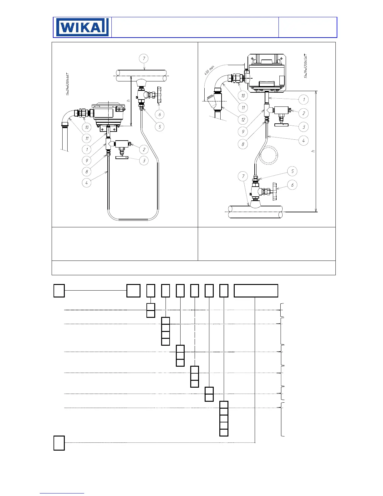
Fig. 21 - Typical installation
Fig. 22 - Typical installation
LEGENDA
1 - Fitting
2 - Drain plug
3 - Service valve
4 - Piping
5 - Three piece fitting
6 - Root valve with drain
7 - Process piping
8 - Three piece fitting
9 - “T” fitting
10 - Three piece fitting
11 - Curve
12 - Blocking joint
NOTE With gas or vapour process fluid, the instrument must be positioned higher than the pipe inlet (see Fig. 20). With a liquid process fluid, the
instrument can be positioned higher or lower, indifferently (see Fig. 19 e 20). In this case, during set point calibration the negative or positive head
must be taken into account (distance h in Fig.19 and 20).
Annex 1 – Model Code
1
MODEL CODE
M
For further information
see datasheet
1.1
Ignition protection mode
W
Weather proof
A
Ex d
1.2
Sensor code
B
Low pressure diaphragm
-
Medium pressure diaphragm
H
Piston
G
Piston with diaphragm
1.3
Sensor material
T
Diaphragm PTFE
X
AISI s.s. or Inconel® 718
K
Monel® 400
1.4
Process connect. material
T
PTFE
X
AISI s.s
K
Monel® 400
1.5
Electric Contacts
U
One
D
Two
1.6
Type of Electric Contact
N
Silver
S
Silver + Argon sealed
G
Gold
O
Gold + Argon sealed
R
Silver adjustable dead band
2
Options
Example: Intrinsic Safety execution
12/2018 WIKA based on 12/2016 CELLA
 Loading...