17WIKA operating instructions pressure transmitter, model S-11
GB
14043046.01 06/2012 GB/D/F/E
6. Commissioning, operation
6.1 Mechanical mounting
■
Remove the protection cap not until shortly before installation.
■
Ensure that the diaphragm of the process connection is not damaged
during installation.
■
The sealing faces at the pressure transmitter and the measuring point
always have to be clean.
■
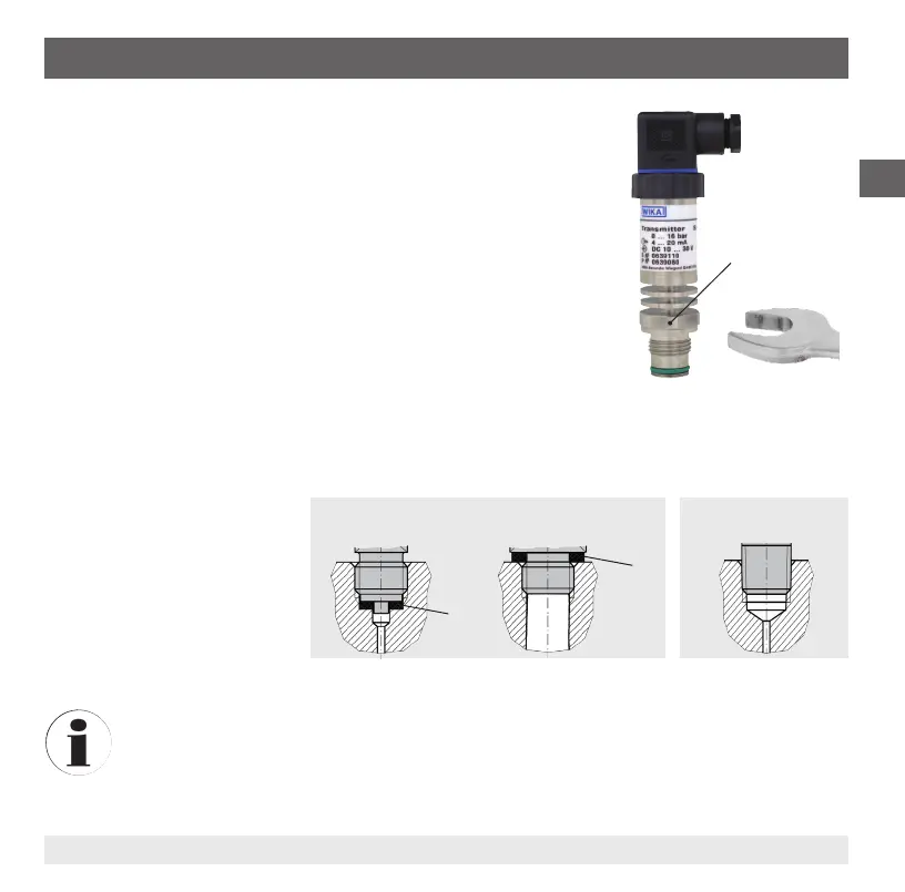
Only ever screw in, or unscrew, the instrument using the spanner
ats. Never use the case or the cooling element as a working surface.
■
The correct torque depends on the dimensions of the process
connection and the gasket used (form/material).
■
When screwing in, do not cross the threads.
■
For information on tapped holes and welding sockets, see Technical
information IN 00.14 at www.wika.com.
■
Attach the connector and screw it in hand-tight. The assembly of the
angular connector is described in chapter 6.2 "Electrical mounting".
Sealing
Correct sealing of the process
connections with parallel threads
at the sealing face
must be
made using suitable at gaskets,
sealing rings or WIKA prole
sealings. The sealing of tapered
threads (e.g. NPT threads) is
made by providing the thread with
additional sealing material such as, for example, PTFE tape (EN 837-2).
For further information on seals see WIKA data sheet AC 09.08 or under www.wika.com.
Spanner ats
Parallel thread Tapered thread
per EN 837 per DIN 3852-E
NPT, R and PT

 Loading...