Installation
Checking the Gas Piping
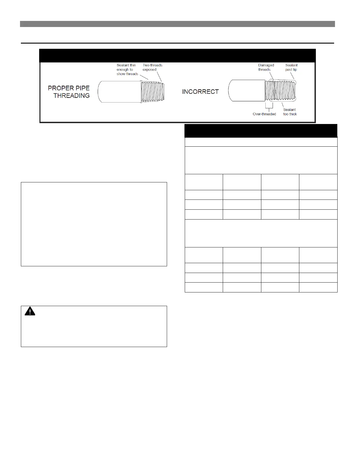
Test all piping for leaks. When checking gas piping to the
furnace with gas pressure at less than 1/2 PSI, shut off manual
gas valve to the furnace. If the gas piping is to be checked with
the pressure at or above 1/2 PSI, the furnace and manual
shutoff valve must be disconnected during testing. Apply a
soap solution (or a liquid detergent) to each joint. Bubbles
forming indicate a leak. Correct even the slightest leak at once.
WARNING: Danger of property damage, bodily
injury or death. Never use a match or open flame
to test for leaks. Never exceed specified
pressures for testing. Higher pressures may
damage the gas valve and cause over firing
which may result in combustion chamber failure.
Liquefied petroleum gas (L.P.G.) is heavier than
air and it will settle in any low area, including
open depressions and it will remain there unless
area is ventilated. Never attempt start-up of the
unit before thoroughly ventilating the area and
smelling near the floor for gas odor.
Natural Gas
Pipe Capacity – Btu/hr.
(includes Fittings)
Pipe Size
L. P Gas
Pipe Capacity – Btu/hr.
(includes Fittings)
Pipe Size
When an existing category I heater is removed or replaced, the original venting system may no longer be sized to properly vent the
attached appliances.
WARNING:
CARBON MONOXIDE POISONING HAZARD
Failure to follow the steps outlined below for each appliance
connected to the venting system being placed into operation
could result in carbon monoxide poisoning or death.
The following steps shall be followed for each appliance connected
to the venting system being placed into operation, while all other
appliances connected to the venting system are not in operation:
1. Seal any unused openings in the venting system.
2. Inspect the venting system for proper size and horizontal pitch,
as required in the National Fuel Gas Code, ANSI Z223.1/NFPA
54 or the Natural Gas and Propane Installation Code, CSA
8149.1 and these instructions. Determine that there is no
blockage or restriction, leakage, corrosion and other
deficiencies which could cause an unsafe condition.
3. As far as practical, close all building doors and windows and all
doors between the space in which the appliance(s) connected
to the venting system are located and other spaces of the
building.
4. Close fireplace dampers.
5. Turn on clothes dryers and any appliance not connected to the
venting system. Turn on any exhaust fans, such as range
hoods and bathroom exhausts, so they are operating at
maximum speed. Do not operate a summer exhaust fan.
6. Follow the lighting instructions. Place the appliance being
inspected into operation. Adjust the thermostat so appliance is
operating continuously.
7. Test for spillage from draft hood equipped appliances at the
draft hood relief opening after 5 minutes of main burner
operation. Use the flame of a match or candle.
8. If improper venting is observed during any of the above tests,
the venting system must be corrected in accordance with the
National Fuel Gas Code, ANSI Z223.1/NFPA 54 and/or Natural
Gas and Propane Installation Code, CSA 8149.1.
9. After it has been determined that each appliance connected to
the venting system properly vents when tested as outlined
above, return doors, windows, exhaust fans, fireplace dampers
and any other gashed burning appliance to their previous
conditions of use.