m
INSTALLING
FURNACE
(Continued)
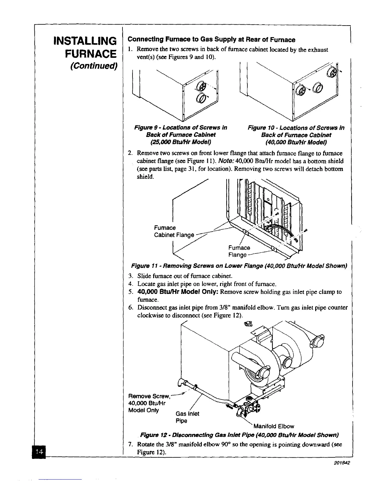
Connecting Fumace to Gas Supply at Rear of Furnace
1. Remove the two screws in back of furnace cabinet located by the exhaust
vent(s) (see Figures 9 and 10).
Figure 9 - Locations of Screws in
Back of Furnace Cabinet
(25,000 Btu/Hr Model)
Figure 10 - Locations of Screws in
Back of Furnace Cabinet
(40,000 Btu/Hr Model)
2. Remove two screws on front lower flange that attach furnace flange to furnace
cabinet flange (see Figure 11). Note: 40,000 Btu/Hr model has a bottom shield
(see parts list, page 31, for location). Removing two screws will detach bottom
shield.
Furnace
Cabinet Flange-
Flange
=a
Figure 11 - Removing Screws on Lower Flange (40,000 Btu/Hr Model Shown)
3. Slide furnace out of furnace cabinet.
4. Locate gas inlet pipe on lower, right front of furnace.
5. 40,000 Stu/Hr Model Only: Remove screw holding gas inlet pipe clamp to
furnace.
6. Disconnect gas inlet pipe from 3/8" manifold elbow. Turn gas inlet pipe counter
clockwise to disconnect (see Figure 12).
Remove Screw,__"
40,000 Btu/I-Ir
Model Only Gas Inlet
Pipe
Aanifold Elbow
Rgure 12 - Disconnecting Gas Inlet Pipe (40,000 Btu/Hr Model Shown)
7. Rotate the 318" manifold elbow 90 ° so the opening is pointing downward (see
Figure 12).