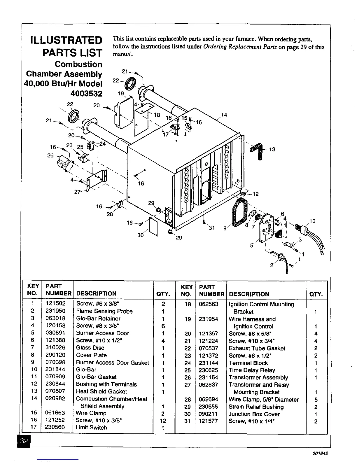
ILLUSTRATED This list containsreplaceable pans used in your furnace. When ordering pa_s,
follow the instructions listed under Ordering Replacement Parts on page 29 of this
PARTS LIST manual.
Combustion
Chamber Assembly 21_,_
40,000 Btu/Hr Model 22-__,_
4003532 19 _',,_
22 20_.
KEY PART
NO. NUMBER
1 121502
2 231950
3 063018
4 120158
5 030891
6 121388
7 310026
8 290120
9 070398
10 231844
11 070909
12 230844
13 070607
14 020982
,I
15 061663
16 121252
17 230560
DESCRIPTION
Screw, #6 x 3/8"
Flame Sensing Probe
GIo-Bar Retainer
Screw, #8 x 3/8"
Burner Access Door
Screw, #10 x 1/2"
Glass Disc
Cover Plate
Burner Access Door Gasket
GIo-Bar
GIo-Bar Gasket
Bushing with Terminals
Heat Shield Gasket
Combustion Chamber/Heat
Shield Assembly
Wire Clamp
Screw, #10 x 3/8"
LimitSwitch
KEY PART
QTY. NO. NUMBERI
2 18 062563
1
1 19 231954
6
1 20 121357
4 21 121224
1 22 070537
1 23 121372
1 24 231144
1 25 230625
1 26 231164
1 27 062837
1
28 062694
1 29 230555
2 30 090211
12 31 121577
1
DESCRIPTION QTY.
Ignition Control Mounting
Bracket 1
Wire Harness and
Ignition Control 1
Screw, #6 x 5/8" 4
Screw, #10 x 3/4" 4
Exhaust Tube Gasket 2
Screw, #6 x 1/2" 2
Terminal Block 1
Time Delay Relay 1
Transformer Assembly 1
Transformer and Relay
Mounting Bracket 1
Wire Clamp, 5/8" Diameter 5
Strain Relief Bushing 2
Junction Box Cover 1
Screw, #10 x 1/4" 2
i
201842