en
20 Installation and operating instructions • Wilo-Control EC-L • Ed.04/2022-09
CAUTION
Do not apply external voltage!
An external voltage which is applied destroys the component.
The level detection for two pumps can be performed using the NW16 level monitor. The
level monitor has the following switching points:
29 28 31 33 34
P1
P2
ON / OFF ON
bk
bn
bk
gy (bu)
gn-ye
bn
Fig.13: Connection diagram NW16 at the
control EC-L 2x...
• Pump 1 On/Off
• Pump 2 On/Off
• High water alarm
The level control corresponds to operation with separate float switches. The internal struc-
ture of the level monitor ensures hysteresis between the activation/deactivation level of the
relevant pump.
Insert the connection cables laid by the customer through the threaded cable glands and se-
cure. Connect the wires to the terminal strip according to the connection diagram.
6.5.8 Connection dry-running protec-
tion/min. Water level with separ-
ate float switch
DANGER
Risk of explosion due to incorrect connection!
If the connected signal transmitter is installed in an explosive atmo-
sphere (Ex zone), there is a risk of explosion due to incorrect connection:
• Do not connect electrode in an explosive atmosphere (Ex zone)!
• Connect the float switch using an Ex cut-off relay!
• Connect level sensor via a Zener barrier!
• Observe the section on explosive atmospheres in the appendix.
• Connection must be carried out by a qualified electrician.
CAUTION
Do not apply external voltage!
An external voltage which is applied destroys the component.
Dry-running protection (“drain” operating mode)
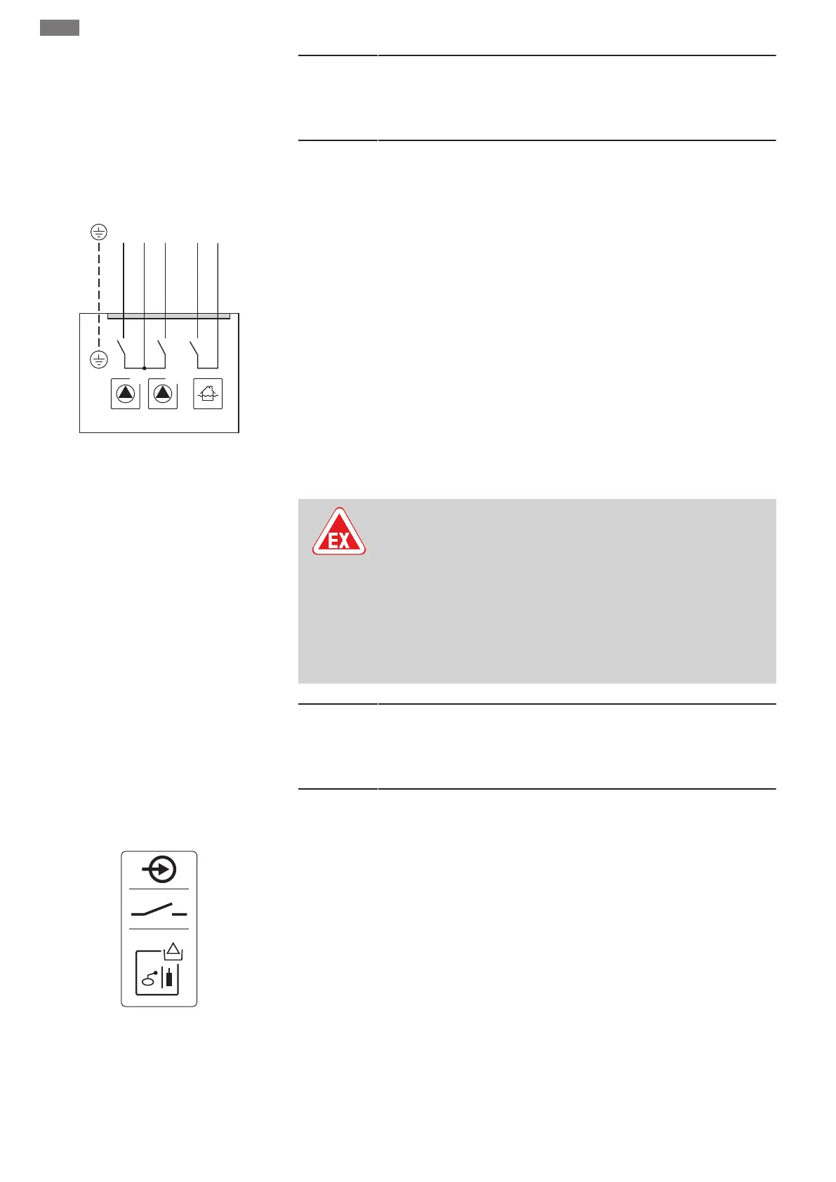
Fig.14: Connection overview symbol
The dry-running level can also be monitored by the following signal transmitters:
• Float switch
• Electrode
– Only Control EC-L1... and EC-L2...
– Hardware version 2 or higher
– Connection is protected against reverse polarity!
The input acts as a normally open contact (NO):
• Float switch open/electrode not immersed: Dry run
• Float switch closed/electrode immersed: No dry run
The terminals are fitted with a converter bridge at the factory.
NOTICE!A separate dry-running protection system is recommended as an additional sys-
tem safety measure.
Insert the connection cables laid by the customer through the threaded cable glands and se-
cure. Remove the converter bridge and connect the wires to the terminal strip according to
the connection diagram. Use the terminal number shown in the connection overview on
the cover.
 Loading...


