en
56 Installation and operating instructions • Wilo-Control EC-L • Ed.04/2022-09
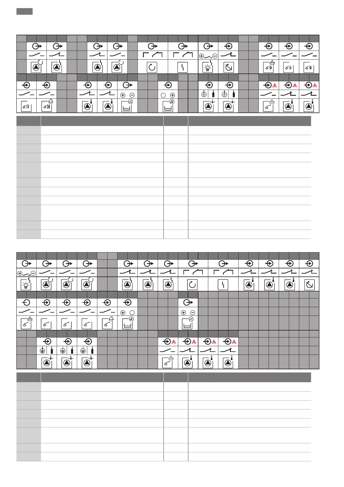
13.4 Terminal diagram overview
Wiring diagram EC-L1... and EC-L2...
1
2 3 4 5 6 7 8 9 10 11 12 13 14 15 16 17 18 19 20 21 22 23 24 25 26 27 28 29
30
55 56 57 58 59 60
31 32 33 34 35 36
37 38 39 40 41 42 43 44 45 46 47 48 49 50 51 52 53 54
1
off
4-20 mA
In
!
1
1
1 2
1
+
2
2
on
1
2
2
on
2
0-10 V
24 V
1 2
!
Terminal Function Terminal Function
2/3 Output: Individual run signal pump 1 31/32 Input: Float switch or electrode “pump 2 in”
4/5 Output: Individual fault signal pump 1 33/34 Input: “High water” float switch or electrode
8/9 Output: Individual fault signal pump 2 37/38 Input: Pump 1 thermal winding monitor
10/11 Output: Individual run signal pump 2 39/40 Input: Pump 2 thermal winding monitor
13/14/15 Output: Collective run signal 41/42 Output: Analogue output for displaying the actual level
value
16/17/18 Output: Collective fault signal 45/46 Input: Level sensor 4–20 mA
19/20 Output: Power output 49/50 Input: Leakage detection pump 1
21/22 Input: Extern OFF 51/52 Input: Leakage detection pump 2
25/26 Input: “Dry-running protection” float switch or elec-
trode
55/56 Input: “Dry-running protection” float switch (ex-mode)
27/28 Input: “All pumps off” float switch or electrode 57/58 Input: Thermal winding monitor pump 1 (ex-mode)
29/30 Input: Float switch or electrode “pump 1 in” 59/60 Input: Thermal winding monitor pump 2 (ex-mode)
Terminal diagram EC-L3...
1
2 3 4 5 6 7 8 9 10 11 12 13 14 15 16 17 18 19 20 21 22 23 24 25 26 27 28 29 30
55 56 57 58 59 60
31 32 33 34 35 36
37 38 39 40 41 42 43 44 45 46 47 48 49 50 51 52 53 54
85 86 87 88 89 90
61 62 63 64 65 66
67 68 69 70 71 72 73 74 75 76 77 78 79 80 81 82 83 84
1
2 3 1 2 3
1
+
2
off on
1 2
on
2 31
1
2 3
4-20 mA
In
0-10 V
24 V
!
1 2 3
Terminal Function Terminal Function
1/2 Output: Power output 33/34 Input: “All pumps off” float switch
3/4 Output: Individual run signal pump 1 35/36 Input: “Pump 1 on” float switch
5/6 Output: Individual run signal pump 2 37/38 Input: “Pump 2 on” float switch
7/8 Output: Individual run signal pump 3 39/40 Input: “High water” float switch
11/12 Output: Individual fault signal pump 1 41/42 Input: Level sensor 4–20 mA
13/14 Output: Individual fault signal pump 2 47/48 Output: Analogue output for displaying the actual level
value
15/16 Output: Individual fault signal pump 3 63/64 Input: Leakage detection pump 1
17/18/19 Output: Collective run signal 65/66 Input: Leakage detection pump 2
 Loading...


