en
28 Installation and operating instructions • Wilo-Control EC-L • Ed.04/2022-09
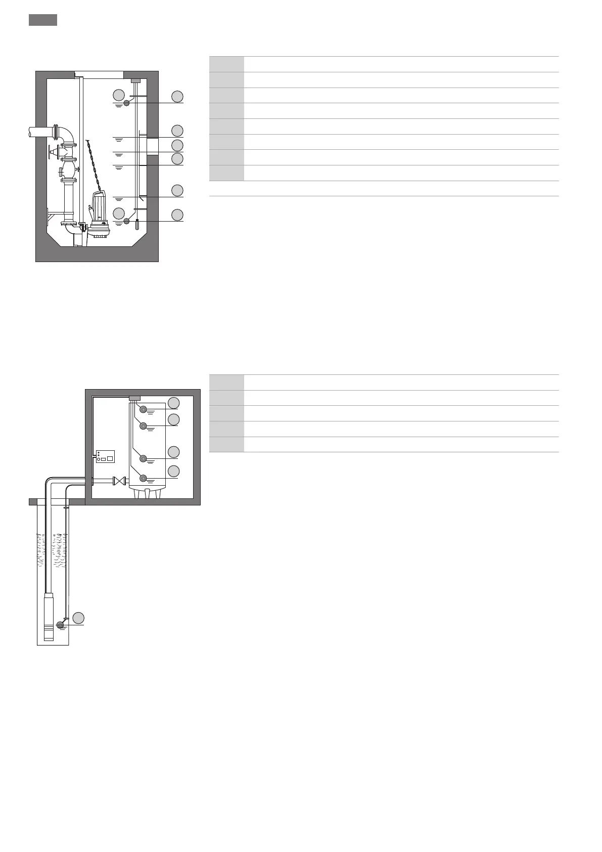
Level measurement with level sensor or dynamic pressure bell
Fig.25: Illustration of the switching points
with a level sensor in the “drain” operating
mode using the example of two pumps
1 Pump 1 On
2 Pump 1 Off
3 Pump 2 On
4 Pump 2 Off
5 Dry-running level
6 High water level
7 High water level*
8 Dry-running level*
* Also implemented via a separate float switch for increased operational reliability.
A level sensor or dynamic pressure bell can be connected. This can be used to control three
pumps:
• Pump 1 On/Off
• Pump 2 On/Off
• Pump 3 On/Off
• Dry-running level
• High water level
7.2.2 “Fill” operating mode
The reservoir is filled up, for instance, to pump water into a rainwater storage tank. The
pumps are activated when the level falls and switched off when the level rises. This control
is mainly used for water supply.
Level control for float switch or electrodes
Fig.26: Illustration of the switching points
with a float switch or electrodes in the “fill”
operating mode using the example of one
pump
1 Pump On
2 Pump OFF
3 High water level
4 Min. water level
5 Dry-running level in the well
Up to a maximum of six float switches or electrodes can be connected. This can be used to
control two pumps:
• Pump 1 On
• Pump 2 On
• Pump 1 and 2 Off
• Min. water level in the tank to be filled
• High water level
• Dry-running level in the well (separate float switch at the “Extern OFF” input)
The float switch should be equipped with a NO contact: Once the switching point has been
reached, the contact is closed.