English
Installation and operating instructions Wilo-Drain MTC 40 13
5.5 Accessories
Accessories must be ordered separately
(see catalogue)
6 Description of the pump
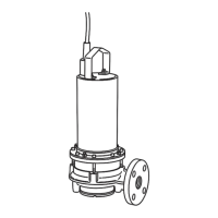
6.1 MTC40 F 16.15/7/1-230-50-2 (fig. 1)
• MTC40 seal kit available through Wilo Service
Department
• MTC40 macerator set available through Wilo
Service Department
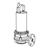
6.2 MTC40 F 16.15/7/3-400-50-2 (fig. 2)
• MTC40 seal kit available through Wilo Service
Department
• MTC40 macerator set available through Wilo
Service Department
7 Installation and electrical connection
DANGER! Risk of fatal injury!
Inappropriate installation or electrical connec-
tion can be life-threatening.
• The installation and electrical connection must
be carried out only by qualified personnel in
accordance with applicable regulations.
• Observe the accident prevention regulations.
7.1 Installation
CAUTION! Risk of damage!
Risk of damage due to inappropriate handling.
Using a chain or rope, suspend the pump only by
the handle or holder – never by the electrical
cable or float cable or pipe/hose connection.
The pump installation site or sump must be free of
frost.
The sump must be cleared of coarse material such
as rubble before setting up and starting the pump.
If the pump is installed in a well, the minimum
dimensions of the well must be 350 mm x 350 mm
x 350 mm. The manufacturer, however, recom-
mends utilisation in wells having dimensions of at
least 450 mm x 450 mm x 450 mm.
The pressure pipe must have the nominal diameter
of the pump (DN40).
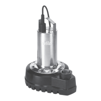
7.1.1 Stationary wet well installation (fig. 3)
• Foot elbow with pump holder, profile joint,
installation and floor fixation accessories and
pipe retainer (item no. 1.1) for dual pipe utilisa-
tion. The guide pipes (R¾" = Ø26.9 in accord-
ance with DIN 2440) must be provided by the
customer.
• Non-return valve with non-constricted pas-
sage, cleaning opening, vent and mounting
accessories
• Gate valve with mounting accessories
• Pipe bend with mounting accessories
• Chain
See catalogue for detailed information.
1. The fixed pipe connections on the pressure
side must be provided by the customer.
2. Using the floor fixing accessories, mount the
foot elbow on the bottom of the sump and
align it.
3. Connect the pressure pipe with the necessary
fittings (accessories) on the foot elbow.
4. Fasten the pump holder and profile joint to the
pressure port of the pump.
5. Mount the R¾" guide pipe (provided by the
customer) on the foot elbow.
6. Suspend the pump in the guide tube, and
lower carefully on the chain. The pump
reaches the correct operating position auto-
matically and seals the pressure port on the
foot elbow through its dead weight.
7. Secure the chain on the guide tube bracket
with shackle (provided by the customer).
7.2 Electrical connection
DANGER! Risk of fatal injury!
Improper electrical connections can lead to fatal
electrical shocks.
• The electrical connection must be carried out
only by an electrical technician approved by the
local utility company.
• Follow the installation and operating instruc-
tions for the pump, level control device and
other accessories.
Item no. Description of component
1 Handle
2 Upper roller bearing
3 Rotor
4 Stator
5 Motor housing
6 Lower roller bearing
7 Bearing housing
8 Mechanical seal on motor side
9 Mechanical seal on pump side
10 Oil chamber housing
11 Impeller
12 Pump base
13 Macerator
14 Seals
15 Float switch
Item no. Description of component
1 Handle
2 Upper roller bearing
3 Rotor
4 Stator
5 Motor housing
6 Lower roller bearing
7 Bearing housing
8 Mechanical seal on motor side
9 Mechanical seal on pump side
10 Oil chamber housing
11 Impeller
12 Pump base
13 Macerator
14 Seals