en Application/use
10 WILO SE 2019-01
Children and persons younger than 16years or with reduced physical, sensory or mental
capacities or limited experience are prohibited from handling the product! A technician
must supervise persons younger than 18years!
3 Application/use
3.1 Intended use
Submersible pumps are suitable for pumping:
ƒ Sewage containing faeces
ƒ Wastewater (with small amounts of sand and gravel)
ƒ Process sewage
ƒ Fluids with dry matter up to max. 8%
3.2 Improper use
DANGER
Explosion due to pumping of explosive fluids!
Pumping of highly flammable and explosive fluids (gasoline, kerosene, etc.) in pure
form is strictly prohibited. There is a risk of fatal injury due to explosion! The pumps
are not designed for these fluids.
DANGER
Danger due to fluids hazardous to health!
If the pump is used in fluids hazardous to health, decontaminate the pump after dis-
mantling and before carrying out any other work! There is a risk of fatal injury! Ob-
serve the specifications in the work regulations! The operator must make sure that
the personnel have received and read the work regulations!
The submersible pumps must not be used for pumping:
ƒ Drinking water
ƒ Fluids containing hard components (such as stones, wood, metal, etc.)
ƒ Fluids containing large quantities of abrasive contents (e.g. sand, gavel)
Intended use also includes compliance with this manual. Any other use is regarded as
non-compliant with the intended use.
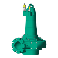
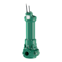
4 Product description
4.1 Design
Submersible sewage pump as submersible monobloc unit for continuous duty in wet
well and dry well installation.
Fig.1: Overview
1 Power supply cable
2 Motor
3 Seal housing
4 Hydraulics housing
5 Pressure port
6 Suction port
4.1.1 Hydraulics
Centrifugal hydraulics with different impeller shapes, horizontal flange connection on
the pressure side, inspection cover as well as casing and impeller wear rings.
The hydraulics are not self-priming, in other words, the fluid must flow in either auto-
matically or with supply pressure.